How to Install Industrial Cabinet Latches on Doors and Panels
Installing an industrial cabinet latch correctly involves far more than drilling a hole and tightening a fastener. Reliable performance depends on the latch type, the product drawing, panel thickness, cutout geometry, grip range, cam, keeper or striker configuration, door alignment, gasket compression and fastener selection. Quarter-turn, compression, draw, rotary and push-to-close latches each rely on different mounting logic and adjustment sequences. As an industrial access-hardware manufacturer, ForndLock works with cabinet builders, enclosure manufacturers and machinery producers to match latch geometry to real door conditions. This guide explains the general installation logic that applies across these latch families, but the product-specific drawing and installation instructions for the exact latch you are using always take priority over any general guidance.
What Should You Confirm Before Installing an Industrial Cabinet Latch?
Before any drilling or fastening begins, you need to confirm the latch type, door and panel construction, cutout geometry, grip range, cam/keeper/striker configuration and fastener requirements defined on the product drawing. Skipping this confirmation step is one of the most common causes of rework on industrial doors and enclosures.
At minimum, confirm the following before starting installation:
· Latch type and operating principle (quarter-turn, compression, draw, rotary or push-to-close)
· Door and frame construction, including material and rigidity
· Panel material and thickness
· Cutout dimensions and orientation
· Grip or clamping range required for the panel
· Cam, keeper or striker geometry specified for the application
· Locked and unlocked positions
· Rotation direction and door handing
· Gasket compression requirements
· Internal clearance for wiring, components or moving parts
· Fasteners and tightening requirements from the manufacturer
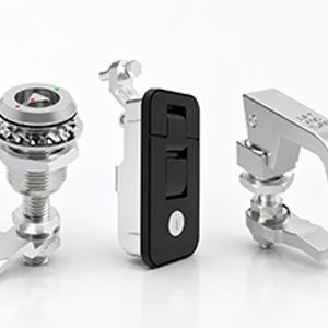
Quarter-turn, compression, draw and rotary latches do not share one universal installation method. A grip range that works for a compression latch on a sealed enclosure will not translate directly to a quarter-turn cam latch on a flush access panel. If you are still deciding between latch families for a new design, it is worth reviewing the differences before finalizing the cutout, since choosing the right latch type for cabinet doors affects almost every downstream installation decision.
How Should the Door and Frame Be Inspected?
The door and frame must be inspected for sag, distortion, uneven gaps and hinge misalignment before any latch is installed, because a latch cannot correct serious structural problems. Check for door sag along the hinge line, panel distortion from prior fabrication or shipping, uneven gaps between the door and frame, hinge alignment, frame deflection under load, gasket condition if one is already fitted, internal obstructions near the intended mounting location, reinforcement ribs that may interfere with the cutout, and clearance around wiring or internal equipment.

If the door does not close evenly against the frame before the latch is installed, no cam, keeper or striker adjustment will fully resolve that condition. Correct the structural issue first.
Before modifying any panel, isolate energized equipment, control sharp edges and metal chips generated during cutting or drilling, and follow the equipment manufacturer's safety procedure for the enclosure being modified.
How Should the Panel Cutout and Mounting Area Be Prepared?
The panel cutout should be prepared from a controlled drawing or installation template that defines exact width, height, corner radius and anti-rotation features, then deburred and re-protected before the latch body goes in. Working from a marked-up sketch instead of the approved drawing is a common source of misaligned or oversized openings.

Confirm the cutout dimensions, diameter (for round bodies), corner radius and any anti-rotation features such as flats or lugs against the drawing before cutting. Round, square, rectangular and double-D cutouts are not interchangeable — the shape determines how the latch body seats and how it resists rotation under repeated operation. Cutout orientation also often determines latch orientation, since many latch bodies only fit one way into a shaped opening.
After cutting, verify edge distance from panel edges or bends and confirm internal clearance for the latch body, cam travel and any wiring or components behind the panel. Deburr the opening completely, since burrs interfere with seating and can damage gaskets or sealing washers. Where the panel has a protective coating, restore corrosion protection on exposed cut edges before installing the latch. Finally, remove all metal chips from the cutting operation — chips left inside an electrical or mechanical enclosure create a real risk of shorts or mechanical interference later.
Why Are Cutout Accuracy and Anti-Rotation Features Important?
Cutout accuracy matters because an oversized opening allows the latch body to rotate or loosen under use, while an undersized opening can damage coatings or distort the housing during installation. D-shaped flats, square openings and locating lugs are designed to control orientation and resist rotation once the latch is torqued into place. Manual reworking of a cutout with a file or grinder can destroy the dimensional control the drawing was built around, even if the opening looks acceptable by eye.
On replacement projects, do not assume the existing cutout matches a new latch's requirements. Measure the actual opening after removing the old latch, since prior installations, rework or wear may have altered it. This article does not provide a universal cutout size, because that dimension always comes from the specific latch drawing.
When Does a Thin Panel Require Reinforcement?
A thin panel needs reinforcement — such as backing plates, large washers, rivet nuts or through-bolts — whenever the mounting area risks deformation, fastener pull-through or fatigue from repeated latch operation. Consider a backing plate or local stiffener when the panel flexes noticeably during test fitting, when a single fastener size cannot achieve adequate thread engagement in the base material, or when the latch will see frequent daily cycling.
Rivet nuts and through-bolts distribute clamping load over a larger area than a single sheet-metal screw. This matters because panel deformation, fastener pull-through and cumulative latch loading are directly connected: a mechanically strong latch can still fail in service if the panel it is mounted to cannot hold that load over time.
How Should Different Industrial Latch Types Be Installed?
Quarter-turn, compression, draw and rotary latches each follow different installation logic because their engagement geometry and adjustment methods are not interchangeable.
Latch type | Main installation reference | Primary adjustment |
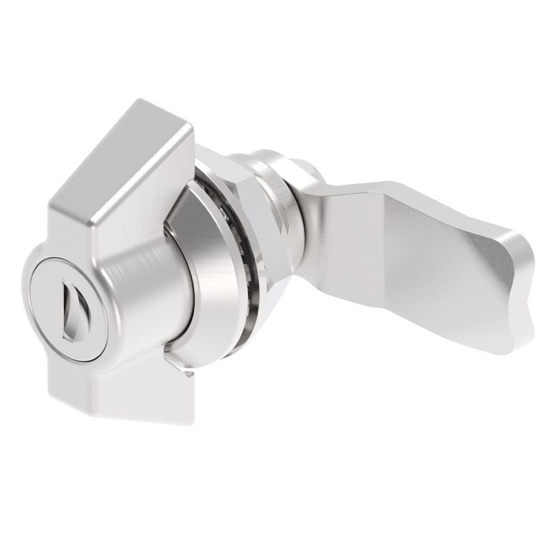
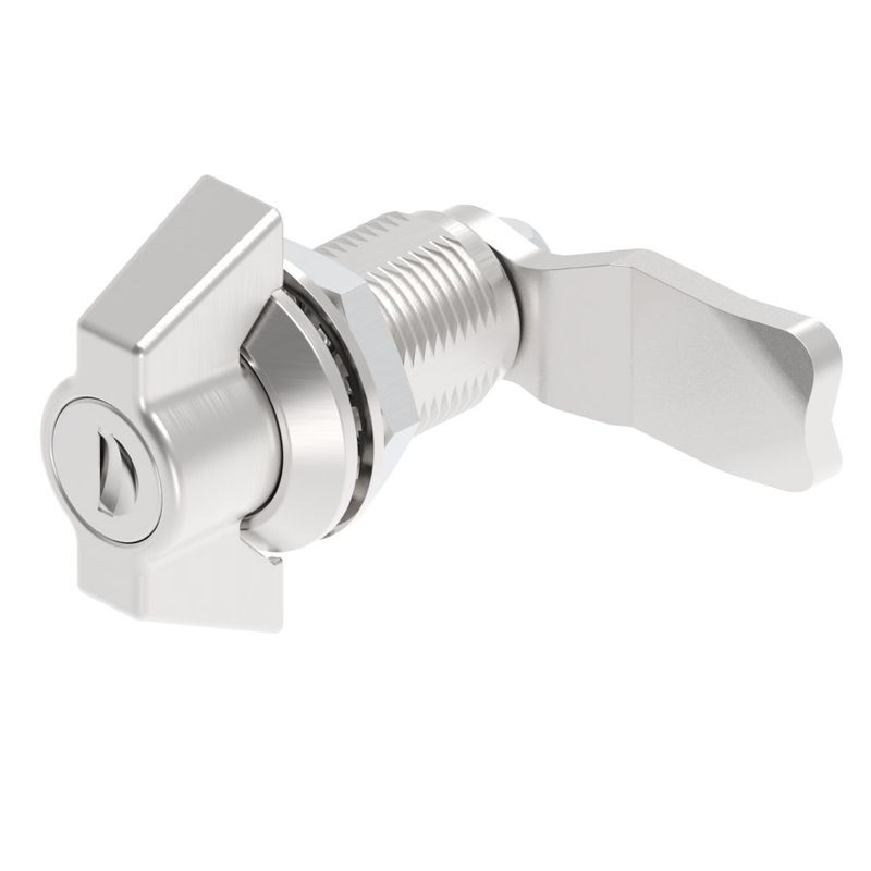
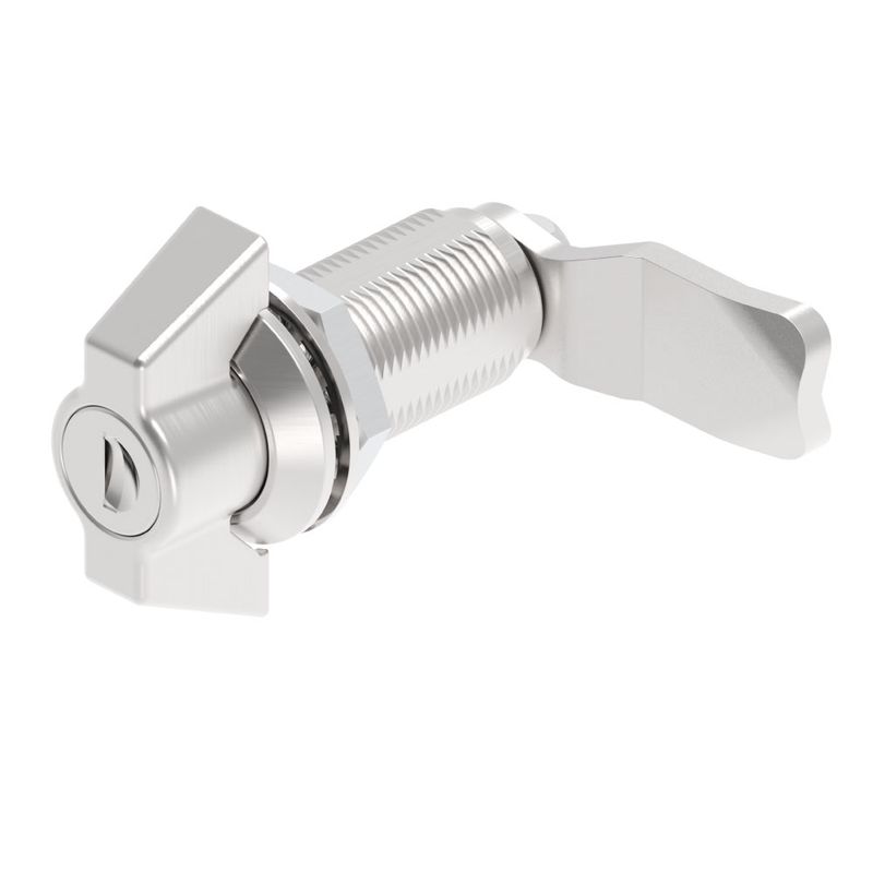
Quarter-turn or cam latch | Cutout, panel thickness and grip | Cam length, offset and orientation |
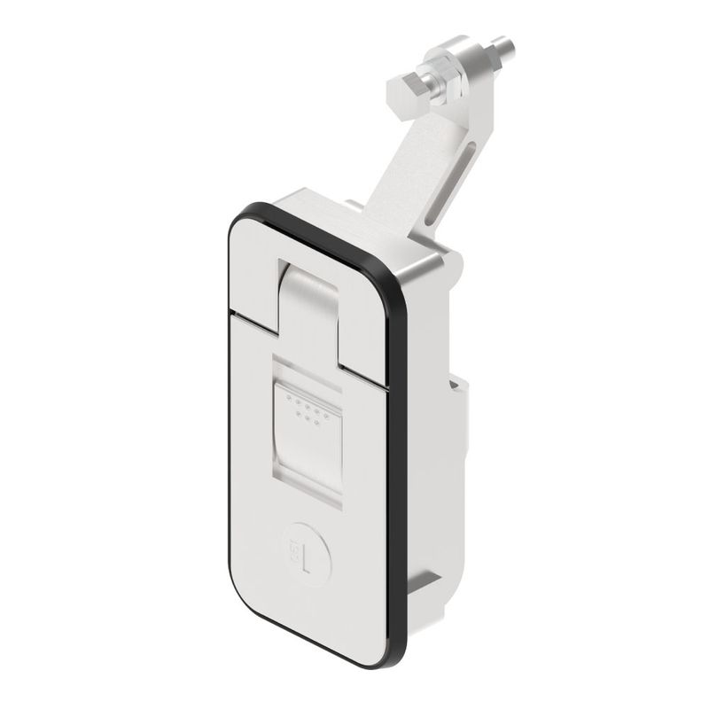
Compression latch | Cutout, grip and compression travel | Gasket preload and operating force |
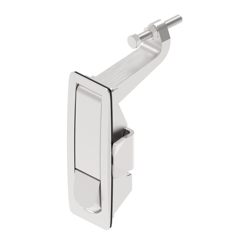
Draw or toggle latch | Latch-to-keeper distance | Clamping tension |
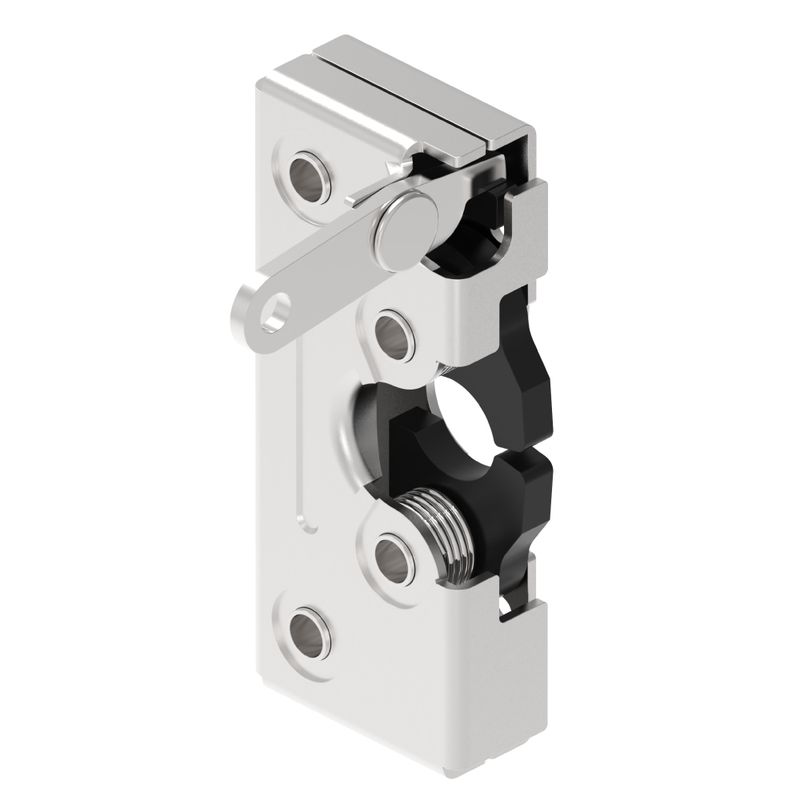
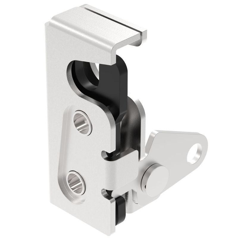
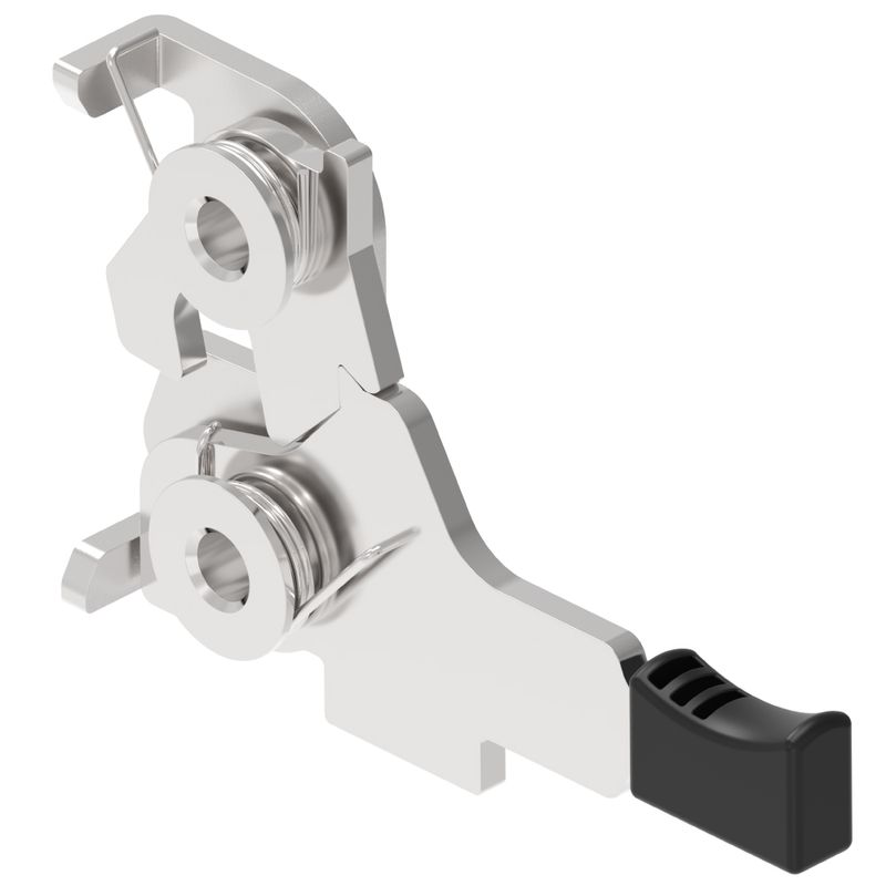
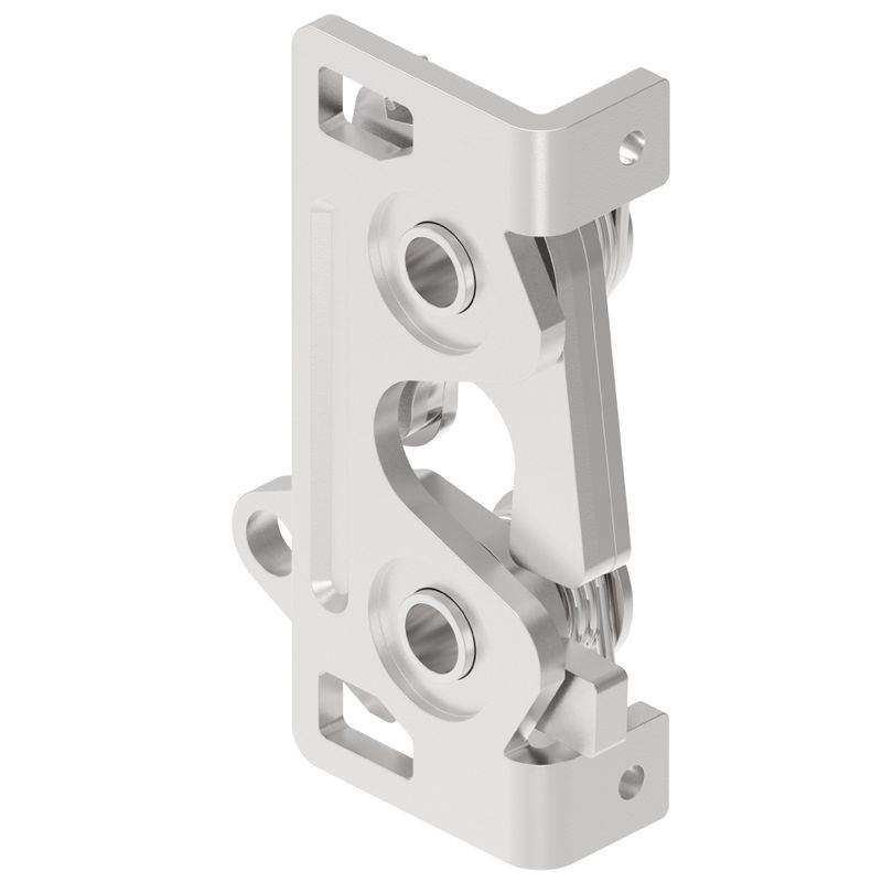
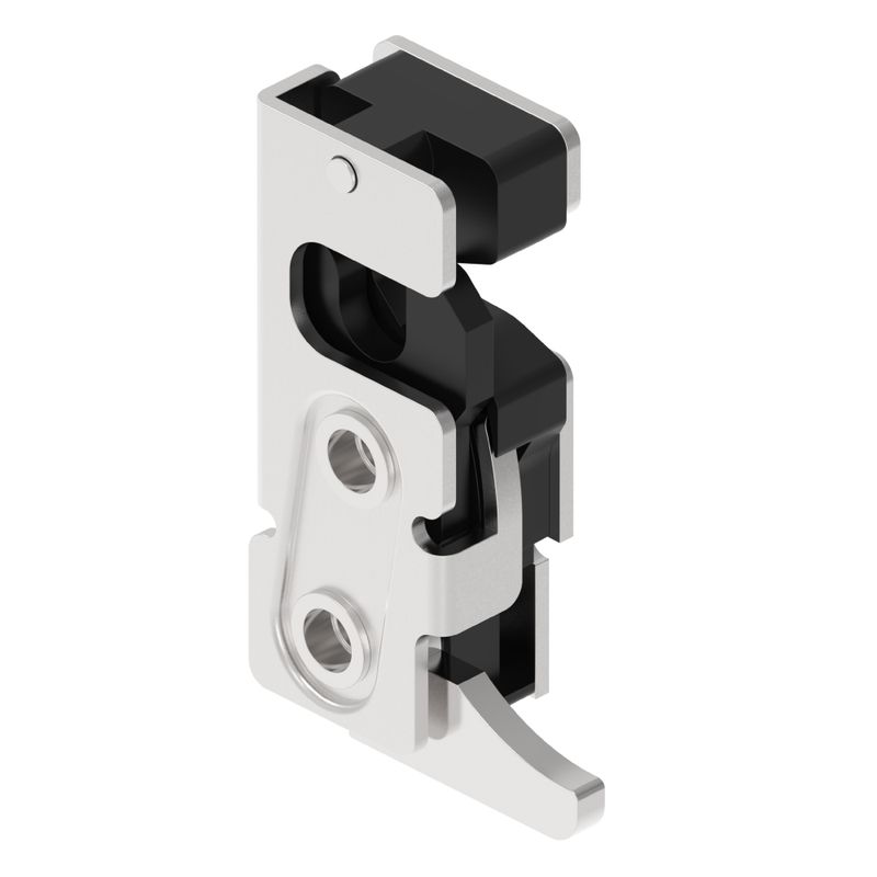
Rotary or push-to-close latch | Latch and striker centerlines | Striker entry and engagement |
For a closer look at cam-specific mounting and swap procedures, our article on installing and replacing cam locks on industrial cabinets covers the sequence in more detail. In general, when we at ForndLock review an installation drawing, we check whether the specified grip matches the actual panel thickness and whether the cam offset is compatible with the keeper location before confirming any part number.
How Should a Quarter-Turn or Cam Latch Be Installed?
A quarter-turn or cam latch is installed by inserting the housing from the specified side, engaging the anti-rotation feature, securing the mounting nut, then fitting the cam in the correct orientation and verifying both locked and unlocked positions. Follow this sequence:
1. Confirm the cutout and the operating direction.
2. Remove components that must be assembled from the rear of the panel.
3. Position the sealing washer correctly, if one is specified.
4. Insert the housing from the specified side of the panel.
5. Engage the anti-rotation feature so the housing cannot spin in the cutout.
6. Install the mounting nut or retaining clip.
7. Install the cam in the correct orientation relative to the keeper.
8. Check both locked and unlocked positions by hand.
9. Verify frame or keeper engagement across the full door swing.
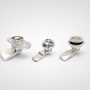
Panel thickness, housing length, grip, cam length and cam offset are related but distinct values. Grip is the range of panel thickness the housing accommodates; cam length and offset determine how far the cam reaches and where it contacts the keeper. This article does not provide universal tightening torque, grip or cam dimensions — those come from the latch drawing for the specific part number you are installing.
How Should a Compression or Draw Latch Be Installed?
A compression or draw latch should be positioned without excessive tension initially, then adjusted progressively for clamping force and gasket compression to avoid overloading the latch or the panel.
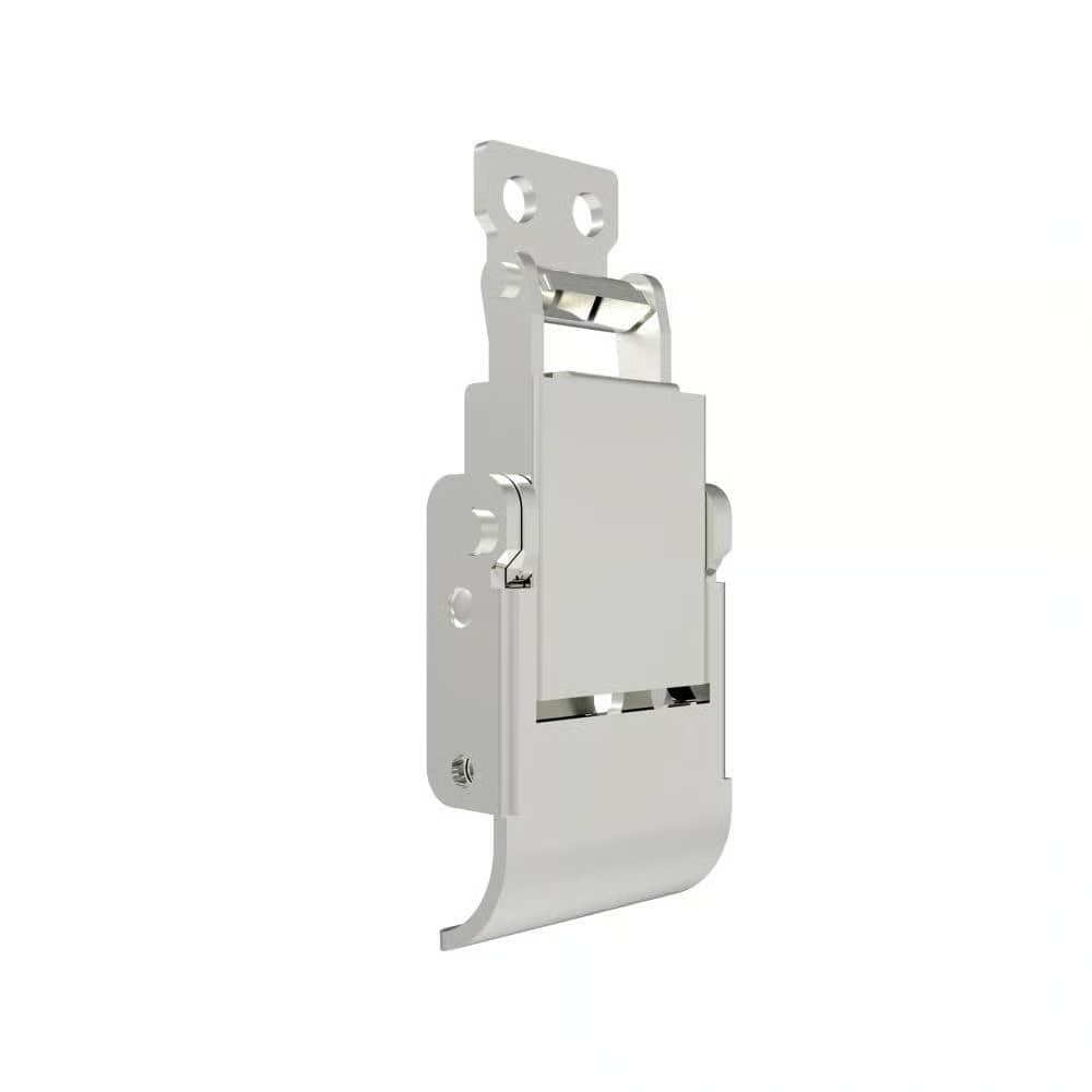
Position the latch and keeper with minimal tension first, and align them so the latch engages the keeper squarely rather than at an angle. Increase clamping tension progressively rather than fully tightening on the first pass. Where the latch design includes over-center engagement, confirm that the toggle or lever reaches full over-center travel without binding.
Check gasket compression uniformly rather than only near the latch itself. When several latches are installed on one door, adjust them in alternating order — tightening one fully before touching the next can create uneven gasket loading across the door. Excessive compression increases operating force, deforms the panel locally, overloads the latch mechanism and can permanently compress the gasket, reducing its sealing ability over time.
How Should a Rotary or Push-to-Close Latch Be Installed?
A rotary or push-to-close latch requires precise alignment of the latch and striker centerlines, with adjustable striker positions used initially and slow-close testing performed before final tightening. Align the latch and striker centerlines as closely as the drawing specifies, and confirm the striker's entry direction matches the door's closing path.

Use the striker's adjustable mounting positions during initial fitting rather than fixing it immediately. Close the door slowly during the first few cycles to confirm alignment before normal-speed operation. Confirm full engagement rather than partial catch, and where the latch has primary and secondary positions, verify both. After release, confirm the latch resets correctly for the next cycle, and check that any release handle, cable or linkage has adequate travel to fully disengage the mechanism. The striker should never be used to force a badly misaligned door into position — if the door needs to be pulled or twisted to reach the striker, the door or frame alignment needs correction first.
How Should the Cam, Keeper, Striker and Gasket Be Adjusted?
Cam, keeper, striker and gasket adjustment happens in three directions — vertical alignment, horizontal engagement and in-and-out compression — and door sag, frame tolerances and gasket condition all affect the final position. Vertical alignment determines whether the cam or striker meets its counterpart at the correct height. Horizontal engagement determines how far the cam or bolt travels into the keeper. In-and-out compression determines how much the gasket is squeezed when the door is fully closed.
Hinges wear, coating thickness varies slightly between production runs, and gaskets compress differently once they have been cycled a few times. All of these factors shift the final adjusted position slightly from the theoretical drawing position, which is why adjustment is normally done on the actual assembled door rather than calculated on paper alone.
How Much Latch Engagement Is Required?
Required engagement must follow the specific latch drawing and load requirements, since both insufficient cam overlap and excessive cam length create operational risk. Insufficient overlap between the cam and keeper can allow the door to pop open under vibration or internal pressure. Excessive cam length can create binding, high operating force, or stress on the latch body and mounting fasteners. A keeper positioned too far from its neutral point can also generate excessive closing force, straining the latch mechanism and the door hinges.
Account for door movement and normal manufacturing tolerances rather than adjusting to a single static position. Always check both locked and unlocked positions after adjustment — a latch that engages correctly but does not release cleanly is as much a problem as one that fails to hold. This article does not provide a universal engagement dimension, since that value is set by the specific latch and application.
How Should Gasket Compression Be Adjusted?
Gasket compression should be increased gradually and checked evenly around the entire door, avoiding local over-compression near the latch itself. First confirm the gasket is seated correctly in its channel or against its mounting surface, with no twists or gaps. Increase compression in small increments rather than fully tightening in one pass, and check compression at multiple points around the door perimeter, not only near the latch.
Avoid concentrating compression near the latch while leaving other areas under-compressed — this is a common result of tightening one fastener fully before checking the others. Insufficient compression typically shows up as door movement under light pressure or visible gaps along the gasket line. Excessive compression shows up as high operating force or visible panel distortion near the mounting points. It is worth being clear that the latch component alone does not establish the environmental rating of the complete enclosure — sealing performance depends on the door, frame, gasket and latch working together as an assembly.
How Should Fasteners, Seals and Grounding Features Be Installed?
Fasteners, seals and grounding features must be matched to the panel material and thickness, tightened to specification, and installed without breaking the coating continuity needed for sealing or grounding.
How Should Mounting Hardware Be Selected and Tightened?
Mounting hardware should match the panel material and thickness, with adequate thread engagement and an appropriate locking method to resist vibration without overtightening. Select fasteners based on the panel material and thickness specified for the application, and confirm thread engagement is sufficient given the material's holding strength. Through-bolts, threaded inserts or backing plates may be needed where sheet metal alone cannot provide reliable engagement.
Overtightening can strip threads, crack coatings or distort thin panels. Insufficient tightening risks loosening under vibration, particularly on doors that are cycled frequently or mounted on moving equipment. Use an appropriate locking method — thread-locking compound, lock washers or nylon-insert nuts, depending on the application — where vibration is a known concern. Where dissimilar metals are in contact, such as stainless fasteners on an aluminum panel, be aware of galvanic-corrosion risk in humid or outdoor environments. Tightening torque must come from the latch, fastener or equipment manufacturer's specification, not from a general rule of thumb.
How Should Sealing and Grounding Features Be Handled?
Sealing and grounding features require correct gasket orientation, clean flat sealing surfaces and properly installed earthing hardware, since powder coating can interrupt electrical continuity if not managed correctly. Confirm the gasket is oriented as specified and that the sealing surface is clean and flat before installation. Avoid excessive gasket extrusion, which can indicate over-compression, and preserve the coating around the installation area wherever sealing performance depends on a smooth, undamaged surface.
Earthing nuts or grounding features must be installed exactly as specified, since powder coating and other protective finishes are electrical insulators and can break continuity if a grounding path is not established through a bare contact point or dedicated grounding hardware. ForndLock can help confirm whether a grounding feature on a latch drawing matches the continuity requirements of your enclosure design. Grounding and environmental performance should always be verified on the complete assembly, not assumed from the latch specification alone. Do not remove coating in an uncontrolled way simply to create a grounding path — this can compromise corrosion protection elsewhere on the panel.
What Should Be Tested and Corrected After Installation?
After installation, the latch must pass functional checks covering orientation, latching, operating force, alignment, sealing and fastener security before the assembly is approved.
Check | Acceptance focus |
Orientation | Correct locked and unlocked positions |
Latching | Full, repeatable engagement |
Operating force | Smooth operation without excessive force |
Alignment | No abnormal rubbing or side loading |
Door retention | No unintended release or excessive movement |
Seal compression | Consistent around the door |
Fasteners | Secure after repeated operation |
Clearance | No interference with wiring or equipment |
Multi-point operation | All points engage and release together |
In one enclosure project we reviewed, a cabinet manufacturer reported that a latch body felt slightly loose in the cutout after initial assembly. Our review found the anti-rotation feature was not fully engaging against the cutout flat. After confirming the actual cutout dimensions and rechecking the grip range against the panel thickness, the mounting orientation was corrected and verified through sample assembly before the configuration was approved for the full production run.
How Should Functional Testing Be Completed?
Functional testing should begin with slow manual operation of the latch, followed by repeated door cycles and full rechecks of fasteners, alignment, gasket compression and clearance.
1. Operate the latch slowly by hand.
2. Confirm the full movement path from open to fully locked.
3. Close and open the door normally, at typical operating speed.
4. Repeat the cycle several times.
5. Recheck fasteners, alignment and operating force.
6. Verify gasket compression and internal clearance.
7. Test multi-point systems for synchronized engagement and release.
8. Perform vibration, cycle or environmental testing where the application requires it.
Testing should always use the actual door, frame, hinges, gasket, keeper or striker and production-intent fasteners — testing on a mockup with different hardware will not reveal the alignment issues that show up on the real assembly.
How Should Common Installation Problems Be Diagnosed?
Installation problems should be diagnosed in a fixed order — starting with the door and frame, then the cutout, cam, keeper or striker alignment, gasket compression, and finally the internal latch mechanism.
Problem | Likely cause | Corrective direction |
Latch body rotates | Oversized cutout or weak anti-rotation engagement | Correct mounting and cutout control |
Door will not latch | Incorrect grip or keeper position | Recheck geometry and alignment |
Door must be slammed | Excessive preload or door misalignment | Correct alignment and reduce compression |
Door rattles | Insufficient engagement or compression | Adjust keeper, cam or latch tension |
Operating force is high | Side loading, excessive preload or poor linkage | Correct geometry before lubrication |
Panel deforms | Weak mounting area or overtightening | Reinforce the panel and correct mounting load |
Water enters near latch | Damaged gasket or poor sealing surface | Reinstall and validate the complete door |
Work through diagnosis in this order: door, frame and hinges; cutout and latch-body mounting; cam, keeper or striker alignment; gasket compression; and finally the internal latch mechanism. Do not bend or force components to compensate for a problem unless the product manufacturer explicitly permits that type of adjustment.
How Can You Complete a Reliable Industrial Latch Installation?
A reliable industrial latch installation follows a controlled sequence — from drawing review and cutout verification through alignment, adjustment, fastening and full-assembly testing — with the approved configuration documented for production.
1. Identify the latch type.
2. Review the controlled product drawing.
3. Inspect the door, frame and hinges.
4. Measure the cutout, panel thickness and grip.
5. Prepare and protect the mounting area.
6. Install the latch body without distortion.
7. Align the cam, keeper or striker.
8. Adjust engagement and gasket compression.
9. Tighten fasteners according to specifications.
10. Test the complete assembly.
11. Record the approved installation configuration.
12. Apply the same controls during production.
A reliable installation means repeatable engagement, acceptable operating force, stable alignment, suitable sealing and secure mounting — not simply a door that can be forced closed.
Need Help Installing or Integrating an Industrial Cabinet Latch?
At ForndLock, we can review your door drawing, panel cutout, thickness, grip, cam or striker geometry, mounting method and sealing requirements. Contact us for latch selection, installation drawing review, cutout and grip evaluation, cam, keeper or striker matching, custom latch development, and sample installation and testing support.
Email: [email protected]