T-Handle Lock Explained: Uses, Types, and How to Choose the Right One
We engineer and manufacture industrial hardware at ForndLock to solve complex physical security and environmental sealing challenges. This technical document breaks down the mechanical principles, structural variants, material properties, and security benchmarks of these locking systems. You will learn how to match latch geometry to panel thickness, evaluate cycle-testing standards, and resolve common installation failures involving cable tension to ensure your hardware performs reliably in the field.
Understanding the Mechanism: How T-Handle Latches Actually Work
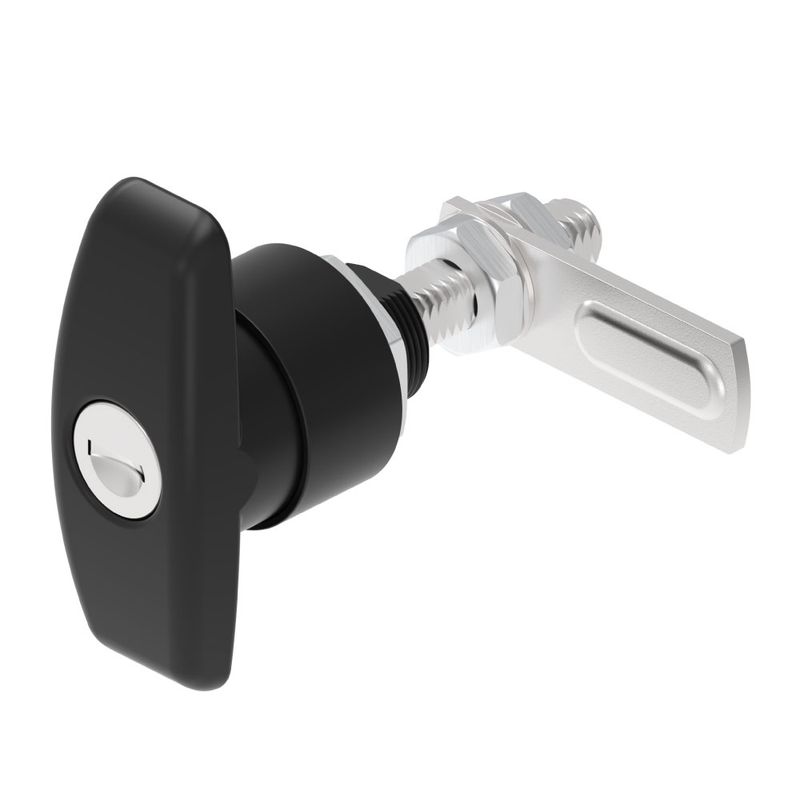
The fundamental mechanical advantage of this hardware lies in its ability to convert rotational torque into linear locking force. The T-shaped handle acts as a double-sided lever arm attached to a central rotating spindle.
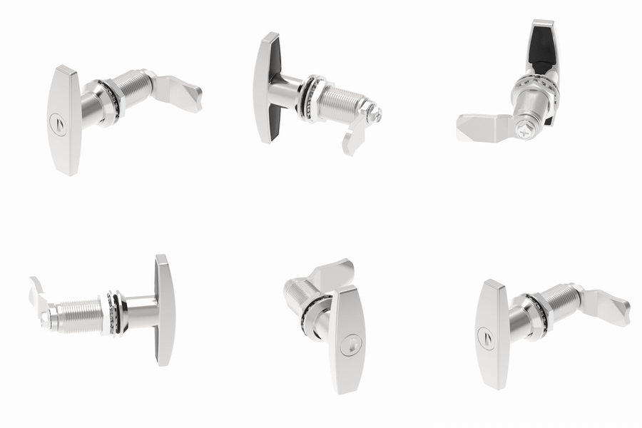
Extending the distance from the point of applied force to the axis of rotation multiplies the input torque. This geometric design allows the operator to generate significant rotational force using minimal hand grip strength.
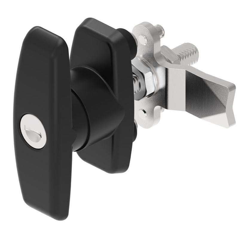
When the operator turns the handle, the internal spindle rotates a connected cam, tongue, or set of actuation rods located on the interior side of the door panel. In compression variants, this rotation does not merely slide a latch behind a frame; it actively pulls the door panel inward along the Z-axis. This linear pulling action is critical for compressing high-density weather seals, such as polyurethane gaskets or EPDM rubber profiles.
Mechanism / Specification Type | Value / Parameter | Reader Impact / Functional Requirement |
Single Point Drop T Latch | 43mm to 55mm panel thickness | Verifies compatible door leaf depth for single-point latch installations. |
3 Point Drop T Latch | 27mm panel thickness | Defines the required mounting profile depth for three-point locking hardware. |
3 Point Actuation Rod Length | 1150mm rod length | Establishes the vertical span coverage inside multi-point enclosure doors. |
3 Point Actuation Rod Stroke | 25mm travel distance | Provides the linear displacement needed to engage remote frame strike plates. |
Square Drive Shaft Variant | 8mm square shaft | Dictates the exact internal cam and follower socket dimensions required. |
ANSI Grade 1 Knob Cycle Test | 800,000 operational cycles | Indicates rotational durability thresholds for high-traffic access points. |
ANSI Grade 1 Knob Weight Test | 360-pound load rating | Sets the vertical downward load threshold before mechanical handle failure. |
ANSI Grade 1 Deadbolt Hammer Test | 10 hammer strikes | Quantifies impact resistance against physical forced-entry attempts. |
Overcoming the reverse friction generated by a highly compressed gasket requires substantial mechanical force. A standard flush knob or low-profile handle often fails to provide sufficient leverage, leading to incomplete sealing or operator fatigue. The extended lever arm of the T-shape solves this by maximizing the torque-to-effort ratio. Furthermore, the internal detent mechanisms and spring-loaded ball bearings ensure that once the handle reaches the fully closed position, it locks into a designated detent, preventing vibration from backing the cam off the strike plate. The mechanism relies entirely on this precise translation of rotational input into linear compression to maintain both security and environmental isolation.
Common Applications: From Ute Canopies to Industrial Cabinets
Compression latches are deployed across sectors where equipment faces constant vibration, exposure to the elements, and the need for rapid, repeated access. In the transportation and recreational vehicle sectors, they secure Ute canopies, cargo trailers, and RV storage compartments. These environments demand hardware that can withstand chassis torsion and high-frequency road vibration without vibrating loose. In the industrial sector, they are the standard choice for heavy-duty toolboxes, telecom enclosures, and electrical distribution cabinets. These industrial applications prioritize dust and water ingress protection to safeguard sensitive electrical components.
Engineers and fleet managers frequently question whether the installation orientation of the handle—specifically horizontal versus vertical—alters the mechanical function or internal cam engagement. The orientation of the external handle does not affect the internal mechanics. The square shaft and the attached cam rotate independently of how the escutcheon plate is riveted to the door. A lock mounted horizontally will engage its strike plate with the exact same linear force as one mounted vertically, provided the cam is clocked correctly during assembly.
Specification / Test Metric | Standard Value | Practical Application / Failure Limit |
ANSI Grade 1 Knob Cycles | 800,000 cycles | Sets threshold for extreme cycle endurance |
ANSI Grade 2 Knob Cycles | 600,000 cycles | Defines operational benchmark for standard use |
ANSI Grade 1 Deadbolt Cycles | 250,000 cycles | Verifies locking mechanism longevity |
ANSI Grade 1 Knob Weight Test | 360-pound load | Confirms vertical load resistance under stress |
ANSI Grade 1 Hammer Blow Test | 10 strikes | Measures deadbolt resistance against blunt force |
Single Point Drop T Panel Fit | 43mm to 55mm | Accommodates thick multi-wall enclosure doors |
Three Point Drop T Panel Fit | 27mm | Requires exact panel sizing for secure mounting |
Three Point Drop T Rod Length | 1150mm | Spans large canopy openings across multi-points |
Three Point Drop T Stroke | 25mm | Dictates travel distance to clear inner frame |
Square Drive Shaft Dimension | 8mm | Matches standard multi-point follower latches |
However, orientation serves a critical operational purpose. Fleet managers routinely standardize vertical handle installation as a visual indicator of security. When a handle is in the vertical position, it provides an immediate, long-distance visual cue to supervisors that the compartment is fully latched and locked. Conversely, a horizontal handle signals an open or unlatched state. This visual management protocol reduces the risk of vehicles moving with unsecured payload doors, making orientation a matter of operational safety rather than mechanical necessity.
The 5 Structural Types of T-Handles and 3 Main Drop T Latches
Selecting the correct structural variant dictates how the hardware integrates with the door panel and internal linkages. The market categorizes these into five distinct structural configurations based on their mounting and actuation methods.
Studded variants feature a threaded rod insert permanently affixed to the base of the handle, designed to pass through a panel and secure into a threaded receptacle on the machine. Tapped variants operate in reverse; the base contains an internal threaded hole, allowing it to be twisted onto an existing threaded fastener protruding from the equipment. Locking variants integrate a keyed cylinder directly into the center of the handle, preventing the spindle from rotating until the correct key disengages the internal wafers. Extra-clearance variants are engineered with a significantly shortened grip length and lower profile to fit into confined spaces where a standard handle would strike adjacent machinery. Through-hole variants feature a threaded channel that runs completely through the handle body, allowing a long bolt to pass entirely through the assembly for specialized mounting requirements.
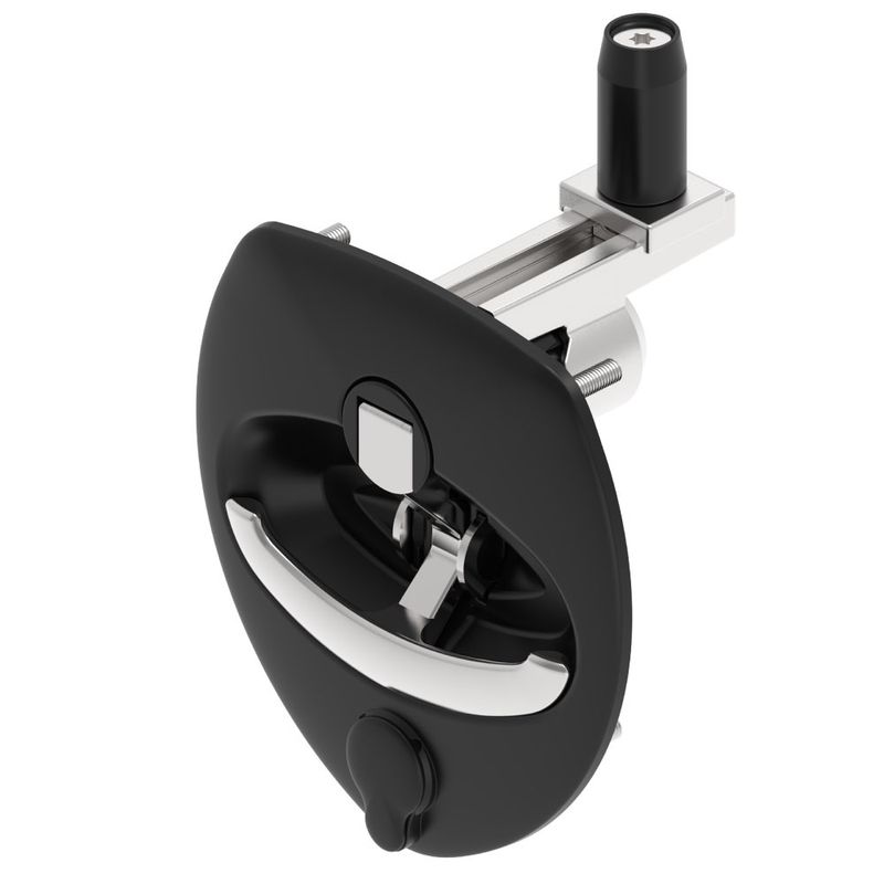
For flush-mounted applications, the Drop T Latch sub-category provides a recessed pan that houses the handle, eliminating protrusions. There are three primary types of Drop T mechanisms.

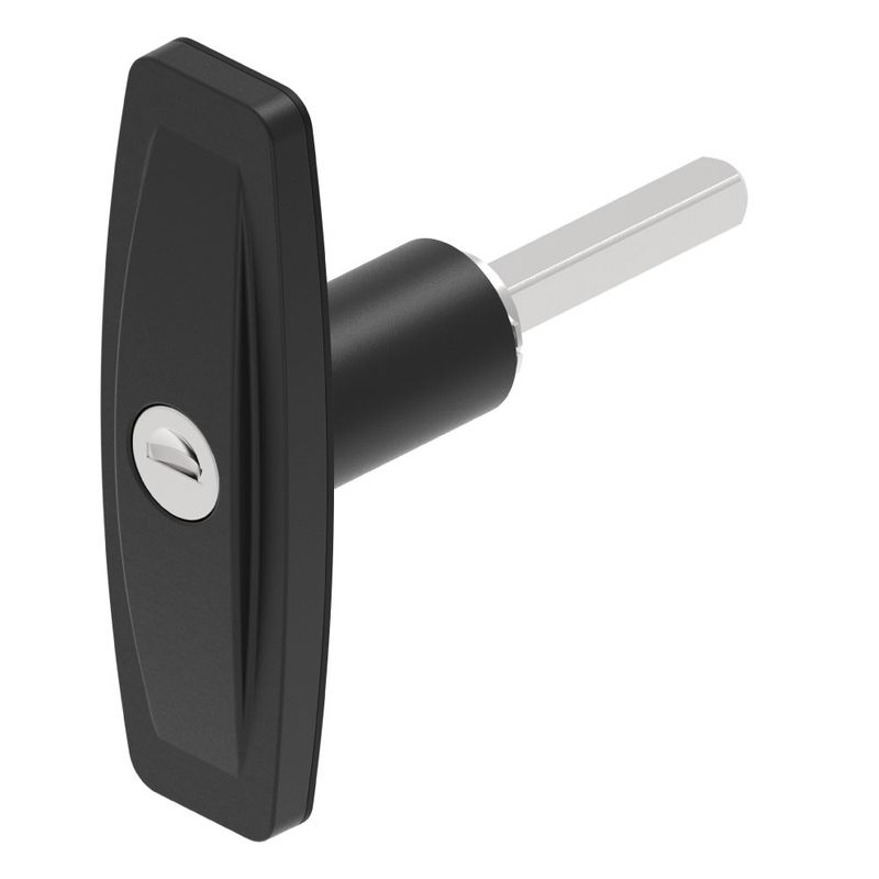
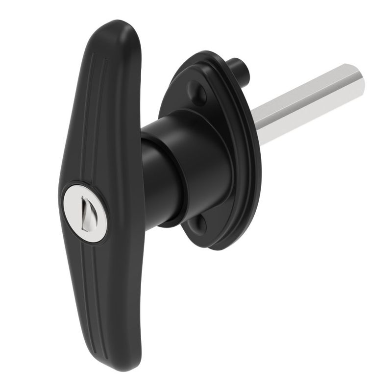
The Single Point Drop T utilizes a single rear tongue to secure the door. The Three Point Drop T utilizes a central latch combined with two actuation rods to secure the door at the top, bottom, and center simultaneously. The 8mm Shaft Drop T features a bare square spindle on the rear, allowing engineers to attach custom cams or linkages for highly specialized internal geometry.
Latch Type | Compatible Panel Thickness | Key Mechanism / Rod Specs |
Single Point Drop T | 43mm to 55mm | Offset tongue adjustment |
Three Point Drop T | 27mm | 1150mm rod length, 25mm stroke |
8mm Shaft Drop T | Varies by accessory | 8mm square shaft |
Accurate specification requires matching the hardware to the exact panel thickness and required linkage travel. If the panel thickness falls outside the 43mm to 55mm range for a single point system, the cam will either fail to engage the strike plate or fail to compress the gasket. Similarly, the 1150mm rods must accommodate the exact vertical height of the door, and the 25mm stroke must clear the frame edges to allow the door to open without binding.
Material Selection: Stainless Steel vs. Zinc Alloy
The longevity of industrial hardware depends entirely on the metallurgical properties of the base material and its surface treatment. The two primary base materials utilized in manufacturing are Stainless steel and Zinc alloy.

Zinc alloy is frequently selected for its excellent die-casting properties. It allows manufacturers to create complex internal geometries, such as integrated cylinder housings and detent tracks, at a lower unit cost. However, zinc alloy is highly susceptible to galvanic corrosion when exposed to dissimilar metals in the presence of an electrolyte, such as saltwater or road de-icing chemicals. Over time, the zinc will pit, oxidize, and eventually seize the internal spindle.
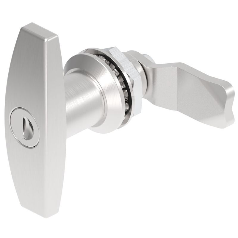
Stainless steel, specifically grades 304 and 316, provides vastly superior mechanical strength and corrosion resistance. The chromium content in stainless steel reacts with oxygen to form a passive, microscopic chromium oxide layer on the surface. If the hardware is scratched, this oxide layer repairs itself instantaneously, preventing rust from penetrating the base metal. For marine environments, coastal Ute canopies, and outdoor electrical cabinets subjected to high salt-spray, upgrading to stainless steel is mandatory to prevent catastrophic hardware failure.
When base Steel is used for cost reduction in dry, indoor environments, it must be protected by a surface coating. Manufacturers typically apply a chrome finish or black powder coating to the steel. A chrome finish provides a hard, wear-resistant surface that protects the steel from ambient humidity and light physical abrasion. A black powder coating involves electrostatically applying a thermoplastic powder and curing it under heat. This creates a thick, durable skin that offers excellent ultraviolet resistance and prevents the underlying steel from oxidizing. However, once the chrome finish or black powder coating is deeply scratched down to the base steel, rapid oxidation will occur.
T-Handle Lock Security Rating Standards Explained
The industrial hardware market currently lacks a unified, official security rating standard specifically dedicated to T-handle locks. Because of this regulatory gap, engineers must reference the rigorous testing protocols established by the American National Standards Institute (ANSI) for commercial door hardware to establish a baseline for acceptable cycle life and physical attack resistance.
High-quality industrial locks should theoretically withstand the physical abuse outlined in these ANSI benchmarks, even if they are not officially certified against them.
1. 800,000 cycles — ANSI Grade 1 door knob safety test standard dictates the benchmark for extreme continuous operation without mechanical failure.
2. 250,000 cycles — ANSI Grade 1 deadbolt safety test standard dictates the benchmark for the extension and retraction of a heavy-duty locking bolt.
3. 600,000 cycles — ANSI Grade 2 door knob safety test standard provides the benchmark for moderate-to-heavy commercial usage.
4. 360-pound — ANSI Grade 1 door knob weight test standard measures the amount of vertical force the handle must withstand without snapping off the door spindle.
5. 10 strikes — ANSI Grade 1 deadbolt hammer strike test standard measures resistance against blunt force physical attacks aimed at shattering the lock housing.
Because most standard utility locks are not engineered to meet these 360-pound weight loads or 10-strike hammer tests, many users report that standard T-handle locks are easy to pry open. The vulnerability usually lies in the thin escutcheon plate, which can flex under the leverage of a crowbar, allowing the cam to slip past the strike plate.
Furthermore, the internal key cylinders often utilize basic wafer mechanisms rather than high-security pin tumblers. Many users report that a specific key code, the 751 Key, is widely distributed and can operate thousands of different utility locks across various brands. Fleet managers initially adopted this single-key system for convenience, allowing one master key to open every toolbox and cabinet on a job site. However, this creates a severe vulnerability, as the 751 Key is essentially a universal passkey available to anyone. To upgrade security, you must specify hardware with restricted keyways, pin tumbler cylinders, and reinforced, heavy-gauge steel backing plates that resist prying.
Selecting the right T-handle locks and latches
Selecting the correct hardware requires a systematic evaluation of the door geometry, environmental exposure, and security threat level. Relying on visual similarity when replacing a lock will result in poor sealing, loose doors, or complete mechanical failure. Follow this engineering-level decision matrix to specify the correct component.
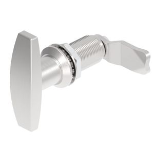
1. Measure the exact panel thickness and grip range. You must calculate the total distance from the outside face of the door to the inside face of the strike plate, factoring in the compression of the weather gasket. If the gasket compresses by 4mm, subtract 4mm from your total grip range. Select a lock with an adjustable cam that covers this specific mathematical range.
2. Determine the requirement for single versus multi-point locking. If the door panel exceeds 1 meter in length or height, a single central latch will not provide enough clamping force at the corners. The corners will bow outward, allowing water ingress and creating a pry point. In these cases, you must specify a three-point locking system to distribute the clamping force evenly across the top, bottom, and center of the frame.
3. Define the environmental sealing requirements. For exterior doors exposed to rain, road spray, or industrial washdowns, the lock housing itself must prevent water from bypassing the spindle and entering the cabinet. We recommend specifying hardware with a minimum ingress protection rating of IP65. This ensures that internal O-rings and polyurethane gaskets block low-pressure water jets, preventing the internal spring mechanisms from rusting and failing.
4. Assess the physical security requirements. If the cabinet contains high-value tools or dangerous electrical components, reject standard wafer cylinders. Specify locks equipped with anti-drill center pins, hardened steel cams, and heavy-duty backing plates that distribute prying forces across a larger surface area of the door panel.
How to Install a T-Handle Lock Replacement Correctly
Replacing a damaged lock requires precise alignment and tension calibration. A misaligned installation will cause the cam to bind against the frame, accelerating wear on the internal spindle and eventually snapping the handle. For systems utilizing cable-driven side latches—common on garage doors and large storage sheds—improper cable tension is the primary cause of failure.

1. Remove the existing hardware and prepare the mounting surface. Drill out the existing rivets or remove the mounting bolts. Scrape away any degraded sealant or adhesive from the door panel cutout. Apply a continuous bead of industrial-grade silicone sealant or position a new die-cut EPDM gasket around the perimeter of the cutout. Do not reuse old, compressed gaskets, as they have lost their elastomeric memory and will fail to prevent water ingress.
2. Mount the new assembly and secure the backing plate. Insert the lock housing through the exterior of the door. Position the steel backing plate on the interior side. Insert the mounting bolts or rivets. Tighten the fasteners in a cross-pattern to distribute the clamping force evenly. Over-tightening one side first will warp the escutcheon plate, causing the handle to bind during rotation.
3. Connect the linkages and calibrate the cable tension. If your system uses a central handle to pull cables connected to side latches, route the cables through the guide pulleys and attach them to the central actuator plate. Many users pull the cables as tight as possible before clamping them down. This is an engineering error. You must leave 2-3mm of slack in the cable. If the cable is tensioned without any slack, the side latches will rest constantly against their strike plates with high static friction. When you turn the handle, the initial rotational force will fight this extreme friction, making the lock feel stiff or causing the lock cylinder to jam entirely. The 2-3mm of slack allows the handle to begin rotating freely, building momentum before the actuator plate engages the cables and pulls the latches smoothly.
Secure Your Equipment with ForndLock
The physical security and environmental integrity of your equipment rely entirely on the precision of your hardware. Specifying the incorrect cam depth, ignoring galvanic corrosion principles, or failing to calibrate linkage tension will result in compromised cabinets and damaged assets. Upgrading to heavy-duty, properly specified locking mechanisms eliminates the vulnerabilities associated with thin escutcheon plates and universal key codes.
ForndLock Industrial Lock Series
We engineer our hardware to withstand severe industrial environments, intense vibration, and physical force. If you require technical assistance calculating grip ranges, selecting the appropriate metallurgy for salt-spray environments, or sourcing multi-point locking systems for a fleet upgrade, our engineering team is ready to assist. Contact us directly at [email protected] to ensure your equipment is secured with exact, application-specific hardware.
Frequently asked questions
What are T handles used for?
T-handles serve as ergonomic gripping, latching, and manual control hardware across industrial machinery, vehicles, and equipment enclosures. They are commonly installed to secure truck toolboxes, cargo trailers, and electrical control panels. The wide grip provides leverage to rotate internal cams or threaded fasteners easily, even when wearing heavy work gloves. In latching setups, specialized models like the Single Point Drop T Latch secure doors with panel thicknesses from 43mm to 55mm, while studded and tapped variations provide direct manual clamping on machines.