Different Types of Bolts: Characteristics, Components and Industrial Uses
Industrial bolts differ in head, shank, thread and body geometry because each joint places different demands on the fastener. Some joints primarily need clamping force, while others also rely on the bolt for alignment, shear transfer, pivoting or component retention. For that reason, diameter and overall length are only part of the specification.
A bolt may pass through the hole and still be unsuitable for the assembly. Head style, available tool clearance, thread pitch and engagement, shank or shoulder geometry, material, strength grade, joint loading and the service environment all influence whether the fastener will perform reliably.
Anatomy of a Bolt: Features That Influence Selection
Several dimensions matter more in practice than the general appearance of the bolt. Head and drive geometry determine how the fastener can be installed and how it bears against the joint. The position of the threaded and unthreaded sections affects load transfer, while thread pitch and usable thread length determine compatibility with the mating component.
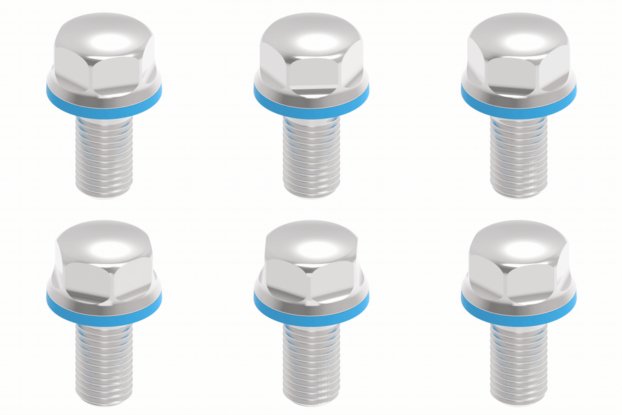
These details become especially important when replacing an existing bolt. Two fasteners with the same nominal diameter and overall length may still behave differently if the head, shank or thread geometry changes.
Head and Drive Style
Head geometry affects both installation access and the way clamping force is transferred into the joint.
A conventional external hex head needs enough radial space for a wrench or socket. In contrast, a socket-head bolt is driven from above and can often be installed where side clearance is limited. This becomes relevant around recessed mounting points, closely spaced components and compact equipment assemblies.
The underside of the head also matters. A larger bearing surface spreads clamping load over a wider area, while countersunk or low-profile heads may be selected when the installed fastener needs to sit flush or remain below surrounding components.
Some head designs also help prevent the bolt from rotating during tightening, which can be useful when access is available from only one side of the assembly.
Shank and Shoulder Geometry
The unthreaded portion of a bolt is not simply unused space between the head and the thread. In many joints, it contributes directly to alignment and shear performance.
Where a bolt crosses a shear plane, placing a plain shank through that interface generally provides a more consistent load-bearing diameter than allowing the threaded section to sit in the same location. Thread roots reduce the effective cross-section and introduce local stress concentrations.
Shoulder bolts serve a more specific purpose. Their shoulder is manufactured to a controlled diameter and can act as a locating surface, guide, bearing surface or pivot for a moving component. In these applications, the shoulder rather than the thread should carry the rotational or locating function.
This distinction is important when selecting bolts for linkages, rollers, hinges and other assemblies where controlled movement or accurate positioning is required.
Thread Geometry and Compatibility
Nominal diameter alone is not enough to confirm that two bolts are interchangeable.
Thread pitch must match the nut or tapped hole, and thread length must suit the required engagement depth. Two bolts can have the same outside diameter but use different thread pitches, making them completely incompatible with the same mating thread.
The transition between the plain shank and threaded section also affects joint behavior. In a partially threaded bolt, that transition may determine whether the shear plane passes through the smooth shank or through the threaded portion.
For replacement or specification work, the minimum information should therefore include nominal diameter, thread pitch, thread length and overall length. Where alignment, shear or movement is involved, the shank or shoulder dimensions should also be checked rather than assumed.
Bolt Features That Change Joint Behavior
Bolt Feature | What It Changes | What the Engineer Should Check |
Head style | Tool access, bearing area, installed profile | Wrench or driver clearance around and above the head |
Drive type | Radial versus axial access requirement | Whether the assembly space allows the driver to reach the head |
Shank | Alignment and shear transfer across the joint | Whether the shank spans the shear plane or the thread does |
Shoulder | Pivot, guide or bearing function | Shoulder diameter, length and transition to the thread |
Thread pitch | Compatibility with the mating nut or tapped hole | Pitch matches the mating thread standard, not just the diameter |
Thread length | Where full engagement begins in the stack | Sufficient full-thread engagement without threads sitting in the shear zone |
Bolt geometry influences assembly, load transfer and serviceability, which is why these features—rather than the overall bolt shape—should guide the first round of selection.
What Are the Main Types of Industrial Bolts?
The main industrial bolt types—hex, flange, carriage, socket head, shoulder, U-bolt, eye and anchor bolts—exist because each solves a different clamping, access, anti-rotation, location, movement or anchoring problem. None of them is universally correct; each represents a structural answer to a specific joint condition, and the depth of coverage below reflects how much engineering judgment each type typically requires.
Hex Bolts
Hex bolts use an external six-sided head so a wrench or socket can engage from outside the joint, which is why they remain the most broadly compatible general clamping option across industrial assembly. The hexagonal head allows tool access from multiple angles, works with both standard and heavy hex configurations, and is available in full-thread and partial-thread versions depending on where the grip length needs to sit.

The variables that actually decide whether a hex bolt fits a specific joint are wrench or socket clearance around the head, the bearing surface under the head, thread pitch matching the mating part, where the thread begins relative to the grip length, and the required strength grade. When radial tool access is genuinely tight—inside a recessed bore or between closely spaced components—a hex head may not be installable at all, and a socket head configuration becomes the more practical option.
Flange Bolts

Flange bolts are not simply a hex bolt with a washer permanently attached; the integrated collar under the head changes how the clamping load is distributed across the bearing surface compared with a standard head resting on a separate washer. This can be useful in equipment assembly and in some formed or sheet-metal structures where a wider, consistent bearing area helps reduce localized surface stress. However, an integrated flange does not automatically eliminate every need for a washer, and it does not solve joint loosening by itself if the underlying preload, vibration or surface condition is not addressed. The variables to check are flange diameter relative to the hole and surrounding clearance, the flatness of the mating surface, actual contact area once installed, and whether the joint material can support that bearing load without local deformation.
Carriage Bolts
Carriage bolts pair a rounded head with a square or ribbed neck meant to resist rotation once the neck properly seats in the mating material—not simply "a bolt with a round head." The intent is to let one side of the joint be tightened without holding the head, because the neck bites into the surrounding material and prevents the bolt from spinning.

This works well when tool access from the head side is limited and a smooth external head is preferred for appearance or clearance reasons. The anti-rotation benefit depends entirely on the neck actually engaging the joint: if the mating material is too soft, the hole is oversized, or the neck cannot seat fully, the bolt will simply spin during tightening and the intended advantage disappears.
Socket Head Bolts
Socket head bolts use an internal drive so the head can be smaller and recessed, but the driver still needs axial clearance even when radial space is tight. That distinction matters because a compact head is often assumed to solve every clearance problem, when in fact the tool—an Allen key, hex bit or torque driver—still needs a straight line of access above the bolt to seat and turn it.

This makes socket head bolts suitable for compact machinery, recessed installation pockets, limited radial clearance around the head, and precision equipment assemblies where a low profile matters. It should not be assumed that a socket head configuration is inherently stronger than other head styles; mechanical performance is set by the material and strength grade specified for that particular bolt, not by the drive style.
Shoulder Bolts
A shoulder bolt's shoulder is a precision bearing or locating surface—not merely an unthreaded section—used to support pivoting, guided or rolling components. The shoulder is sized to a specific diameter and length so that a bushing, roller, link or bracket can rotate or slide against it with a controlled fit, while the threaded end secures the bolt into the fixed part of the assembly. The parameters that matter are shoulder diameter, shoulder length relative to the moving component's thickness, thread size at the fixed end, and the transition geometry between shoulder and thread.

If a moving component is instead allowed to rotate directly on a standard bolt's threaded section, the result is often poor alignment, uneven wear on the mating part, and eventual thread damage from repeated contact stress. Switching to a shoulder bolt is not an automatic fix; whether it resolves the problem depends on the surrounding joint design, including how the shoulder length relates to the stack it passes through. At ForndLock, our engineering team checks shoulder diameter, length and transition geometry against the mating component before confirming a configuration, because a shoulder that is even slightly too long or too short changes how the moving part is supported.
U-Bolts
U-bolts use a U-shaped body to capture a pipe, tube or bracket against a mounting surface, with clamping force set by leg length, bend geometry and thread length together rather than by rod diameter alone. This makes them a common choice for pipe supports, tube clamping, bracket retention and general equipment support where a round or shaped component needs to be held against a fixed surface.

The parameters that decide fit are rod diameter, inside width and height of the bend, leg length, thread length available past the mounting plate, and the bend radius itself. Overtightening a U-bolt can crush a thin-wall tube, damage a coating, or deform the supported component, so selection cannot be based on matching pipe diameter to inside dimension without also considering wall thickness and how much clamping force the supported part can actually tolerate.
Eye Bolts
An eye-shaped bolt provides an attachment point, but whether it is suitable for lifting depends on its specific design, specification, installation and load direction—not the eye shape alone. There is an important distinction between a general attachment eye, used for securing a cable or restraining a component, and a rated lifting application, which requires a product specified and installed for that purpose with the load applied in the direction the eye is designed for.

The variables that matter are the eye geometry itself, thread size and engagement, whether the design includes a shoulder, the direction the load will be applied relative to the eye's plane, and the base material's ability to support that load. No lifting capacity figures are provided here, because a safe working load depends on the specific product specification and installation, not on the general appearance of an eye bolt.
Anchor Bolts
Anchor bolts connect machinery or steel structures to concrete or a foundation, and selecting one is a system-level decision involving the base plate and foundation, not just the bolt. The bolt itself is only one part of the load path; the base plate distributes load into the bolt pattern, the foundation has to accept that load without cracking or pulling out, and the embedment depth has to suit the load direction, whether primarily tensile, shear or a combination of both.

This is not a building-code discussion, but it is worth stating plainly that anchor bolt selection cannot be reduced to matching a diameter to a hole pattern; the installation method, whether cast-in-place or post-installed, also changes what performance can reasonably be expected from the same bolt.
Specialty and Custom Bolts
Specialty bolts such as J-bolts, hook bolts and other formed variants rely on geometry itself to perform part of the function, which means thread size alone is never enough to specify them.

A J-bolt's bend radius and leg length are as functional as its thread, since they determine what the bolt hooks around or how it embeds; a hook bolt's bend angle determines how it engages a purlin or structural member. These designs sit outside the standard head-and-shank pattern of the previous types, and specifying them by thread diameter without dimensioned drawings of the formed section is one of the more common sources of mismatched parts in custom orders.
Industrial Bolt Type Comparison
Bolt Type | Defining Feature | What It Solves | Typical Industrial Use | Critical Selection Point |
Hex Bolt | External six-sided head | General clamping with broad tool access | Machinery frames, general assembly | Wrench clearance and thread pitch match |
Flange Bolt | Integrated collar under the head | Wider, more consistent bearing surface | Equipment housings, formed metal joints | Flange diameter versus contact area |
Carriage Bolt | Rounded head with anti-rotation neck | One-side tightening without holding the head | Panels, brackets, wood-to-metal joints | Neck engagement with the mating hole |
Socket Head Bolt | Internal drive, compact head | Installation in recessed or tight spaces | Compact machinery, precision assemblies | Axial driver access above the head |
Shoulder Bolt | Precision bearing shoulder | Pivoting or guided movement | Linkages, rollers, guided mechanisms | Shoulder length matched to moving part |
U-Bolt | U-shaped capturing body | Retaining pipe, tube or brackets | Pipe supports, equipment mounting | Inside dimensions and wall tolerance |
Eye Bolt | Looped attachment head | Providing a defined attachment point | Cable anchoring, restraint points | Load direction versus eye orientation |
Anchor Bolt | Foundation-embedded fastener | Connecting structures to concrete | Machine bases, structural columns | Base plate, embedment and load direction |
Different bolt types exist because joints impose different requirements for clamping, access, anti-rotation, location, movement or anchoring, and no single type satisfies all of them at once.
Which Characteristics Actually Change Bolt Selection?
Within a single bolt type, thread pitch, thread length position, material, finish and strength grade—not appearance—determine whether two bolts of the same diameter are actually interchangeable. Two hex bolts can look identical on a shelf and still be unsuitable substitutes for one another once these characteristics are examined.
Why Do Diameter and Pitch Both Matter?
Diameter alone does not complete a specification because two bolts of the same nominal size can still use different pitches, making them incompatible with the same nut or tapped hole. A bolt described only as "M10" leaves the pitch, the mating thread standard and the required engagement length undefined, and a fine-pitch and coarse-pitch bolt at the same nominal diameter will not thread into the same nut.
Does Thread Position Matter More Than Length?

What matters is not how much of the bolt is threaded, but where the threaded portion sits within the assembled joint, especially across a shear plane. In structures where the bolt carries shear load, having the thread root positioned across that shear plane rather than the plain shank changes how the joint responds under load, because the thread reduces the effective diameter at that location. This is a design consideration to review case by case rather than a fixed formula to apply universally.
How Do Material and Finish Interact?
Material and finish selection depends jointly on mechanical requirement, operating environment, mating material and coating. Carbon steel, alloy steel and stainless steel each suit different combinations of load and environment, and a zinc-plated or otherwise coated steel bolt can outperform an unsuited stainless option in some applications, while underperforming in others. In our experience, a stainless bolt is sometimes selected without checking the mating material or the environment, which is a review point our team looks at during material and finish review, since galvanic interaction between dissimilar metals or an unsuited coating can undermine the intended corrosion resistance entirely.
Is Strength Grade a Separate Decision From Bolt Type?
Bolt type and strength grade are separate decisions—two hex bolts can look nearly identical while carrying different mechanical properties, so a replacement cannot be judged by diameter or appearance alone. A grade marking on the head, where present, is the only reliable indicator of mechanical property class; visual similarity in head shape, size or finish tells a buyer nothing about tensile or yield performance.
Is There Enough Bearing Area and Tool Access?
Head bearing area and tool access must be checked together: enough space to seat the head is meaningless if the tool cannot actually reach it during assembly. A joint drawing should confirm whether the contact surface under the head is large and strong enough for the intended clamping load, and whether the head interferes with nearby components once the assembly is closed up.
Characteristics That Make Similar Bolts Non-Interchangeable
Characteristic | What Can Differ | Risk If Ignored |
Pitch | Coarse versus fine thread at the same diameter | Bolt will not engage the mating nut or tapped hole |
Thread length | Where full engagement begins in the grip | Reduced thread engagement or thread sitting in a shear zone |
Strength grade | Tensile and yield properties at the same size | Under-strength bolt used in a load path requiring more |
Material | Carbon steel, alloy steel, stainless steel | Wrong corrosion resistance or unsuitable mechanical response |
Finish | Plating, coating or bare surface | Accelerated corrosion or galvanic reaction with mating parts |
Head dimensions | Bearing diameter and head height | Insufficient bearing area or head interference with nearby parts |
Shank / shoulder | Plain length, diameter and transition geometry | Poor alignment, uneven wear, or loss of intended locating function |
How Should the Bolt Match the Joint?
The bolt should be matched to the joint function it must perform—clamping, locating, pivoting, retaining pipe or anchoring—rather than to an industry category such as automotive or construction. Organizing selection by function keeps the decision tied to how the joint actually behaves, regardless of which industry the equipment belongs to.
What Fits General Clamped Joints?
General clamped joints are typically evaluated first against hex or flange bolts, checked against joint stack, bearing area, tool access, grip and preload requirements. The joint stack thickness sets the grip length needed, and bearing area under the head has to be adequate for the clamping preload the joint requires.

What Works When Tool Access Is Limited?
Socket head bolts are usually evaluated when radial space is tight, but limited radial clearance does not remove the need for axial driver access. A designer confirming a socket head configuration should still verify a straight approach path for the driver above the bolt, not just clearance around it.
What Suits Pivoting and Guided Components?
Shoulder bolts suit pivoting or guided components, provided the shoulder—not the threaded section—is designed to be the actual locating or bearing surface. The shoulder length has to match the thickness of the moving part it supports, or the intended guiding function will not be realized as designed.
Match the Bolt Type to the Joint Requirement
Joint Requirement | Bolt Type to Evaluate | Why It Fits | What Must Be Verified |
General clamping | Hex or flange bolt | Broad tool access and bearing area | Joint stack, grip length, preload |
Limited tool access | Socket head bolt | Compact head, internal drive | Axial driver access above the bolt |
Anti-rotation from one side | Carriage bolt | Square neck resists rotation | Neck engagement with the mating material |
Pivot or guided movement | Shoulder bolt | Dedicated bearing shoulder | Shoulder length versus moving part thickness |
Pipe or tube retention | U-bolt | Captures round or shaped components | Wall thickness, inside dimensions, bend geometry |
Foundation anchoring | Anchor bolt | Transfers load into concrete | Base plate, embedment, load direction |
Attachment point | Eye bolt | Defined loop for cable or restraint | Load direction and correct product rating |
Why Can the Right Bolt Type Still Fail?
The correct bolt category can still fail because failure usually comes from how the joint is specified and installed, not from choosing the wrong family of bolt. A hex bolt selected correctly for a clamped joint can still loosen, strip, bend or crush the surrounding material if the surrounding joint conditions are not addressed, which is why understanding how nuts, bolts and washers work together in an assembled joint matters as much as picking the bolt type itself.
When the Bolt Type Looks Right but the Joint Still Fails
Failure Symptom | Likely Joint Issue | What to Review |
Bolt repeatedly loosens | Insufficient preload or vibration | Preload level, locking strategy, joint movement |
Threads strip | Inadequate engagement or soft tapped material | Thread engagement length, mating material hardness |
Bolt bends | Shear load exceeds the bolt's load path capacity | Load direction, shank position, joint alignment |
Surface crushes under head | Bearing area too small for the clamping load | Head diameter, washer use, base material hardness |
Corrosion develops | Material or finish unsuited to the environment | Material, finish, mating-part compatibility |
Assembly cannot be serviced | Tool access blocked after final assembly | Head clearance, driver approach path, surrounding parts |
Fracture occurs near threaded region | Thread positioned across a high-stress load plane | Thread location relative to shear plane, strength grade |
Is Bolt Loosening Always a Bolt-Type Problem?

Bolt loosening is frequently a preload, vibration or joint-movement issue rather than a bolt-type issue. Insufficient preload, cyclic vibration, movement between mating surfaces, or settlement of a gasket or coating can all cause loosening independent of which head style was chosen, and no single locking method resolves every cause; the underlying joint condition has to be diagnosed first.
Does a Stronger Bolt Always Create a Stronger Joint?
A higher-grade bolt does not automatically create a stronger joint, because joint strength also depends on the nut, the tapped material, the washer, the base material, the contact area, the preload and the overall joint geometry. Upgrading the bolt alone while leaving an undersized nut, a soft tapped hole or an inadequate bearing surface unchanged simply shifts the weak point elsewhere in the assembly rather than removing it.
When Is a Standard Bolt Not Enough?
A standard bolt stops being enough once the joint imposes a constraint that no catalog configuration satisfies, such as head clearance, shoulder length, thread position, material or geometry that falls outside standard ranges. Recognizing this boundary early avoids forcing a standard part into a joint it was never designed to fit.

Common triggers include a standard head interfering with nearby equipment once the assembly is closed, a shoulder length that simply does not exist in a standard catalog, a thread that needs to begin at a specific point in the grip rather than a standard position, a standard shank that cannot locate a component precisely enough, a material or finish combination that standard stock does not offer, or a formed geometry—such as a specific hook angle or bend radius—that has to be custom-made from the start.
When to Consider a Custom Bolt
Design Constraint | Why a Standard Bolt May Not Fit | Possible Custom Variable |
Limited head clearance | Standard head height or diameter interferes with adjacent parts | Reduced head profile or custom drive style |
Precise shoulder requirement | Standard shoulder lengths do not match the moving component | Custom shoulder diameter and length |
Special joint stack | Standard grip length does not align thread position correctly | Custom grip length and thread start point |
Non-standard thread length | Standard thread length leaves too much or too little engagement | Custom thread length for the specific stack |
Custom equipment interface | Mating part geometry does not match any standard head or shank | Custom head or shank profile |
Environmental requirement | Standard material or finish does not suit the exposure | Alternative material or coating specification |
Formed or hooked geometry | Function depends on a bend, hook or special form | Fully custom formed dimensions |
At ForndLock, custom bolt reviews focus on the drawing, the mating parts, the dimensions involved, the thread specification, the material, the finish, the intended application and the quantity required. A request such as "I need an M10 bolt" is often not enough to determine whether the fastener will actually fit the joint it is meant to serve, and for early-stage or lower-volume custom projects, sourcing low MOQ fastener suppliers for custom bolt projects can be a practical way to validate a design before committing to larger production runs.
Conclusion
A bolt is only right when it is right for the complete joint, not simply when it matches a diameter and length called out on a drawing. The same bolt can be wrong if the thread pitch does not match the mating part, if the shank or shoulder sits in the wrong position, if head clearance blocks the tool, if the material does not suit the environment, or if the joint load exceeds what the full assembly—not just the bolt—can carry.
When a standard bolt cannot meet head clearance, shoulder dimensions, thread position, material, finish or a special geometry requirement, the next step is usually a drawing review rather than a further search through a general catalog. Sending a bolt drawing, a joint drawing, mating component dimensions, thread specification, application requirements and quantity to [email protected] lets ForndLock evaluate whether an existing standard configuration can be adapted, or whether dimension customization, thread or shoulder geometry changes, a different material or finish, sample validation and custom production are the more appropriate path forward.