
Over-Center Draw Latches: Types, Uses and Manufacturer Guide
An over-center draw latch uses a handle, pivot and linkage to pull two components together and hold them closed once the mechanism travels past its center point. Selecting the right over-center draw latches for a project depends on far more than overall size. Engineers need to evaluate over-center travel, mounting geometry, required clamping action, static and dynamic loads, installation tolerances, operating environment, material selection and the manufacturer's testing data. Load-rating terminology and test conditions vary between suppliers, so a single unexplained maximum-load figure is not a reliable basis for comparison. This guide, prepared from ForndLock's perspective as an industrial latch manufacturer, walks through mechanism behavior, configuration choices, materials, applications, selection criteria and manufacturer evaluation.
How Does an Over-Center Draw Latch Generate and Maintain Clamping Force?
An over-center draw latch generates clamping force through a handle-and-linkage system that pulls a hook or bail against a keeper, then locks the geometry in place once the mechanism travels past its dead-center point.

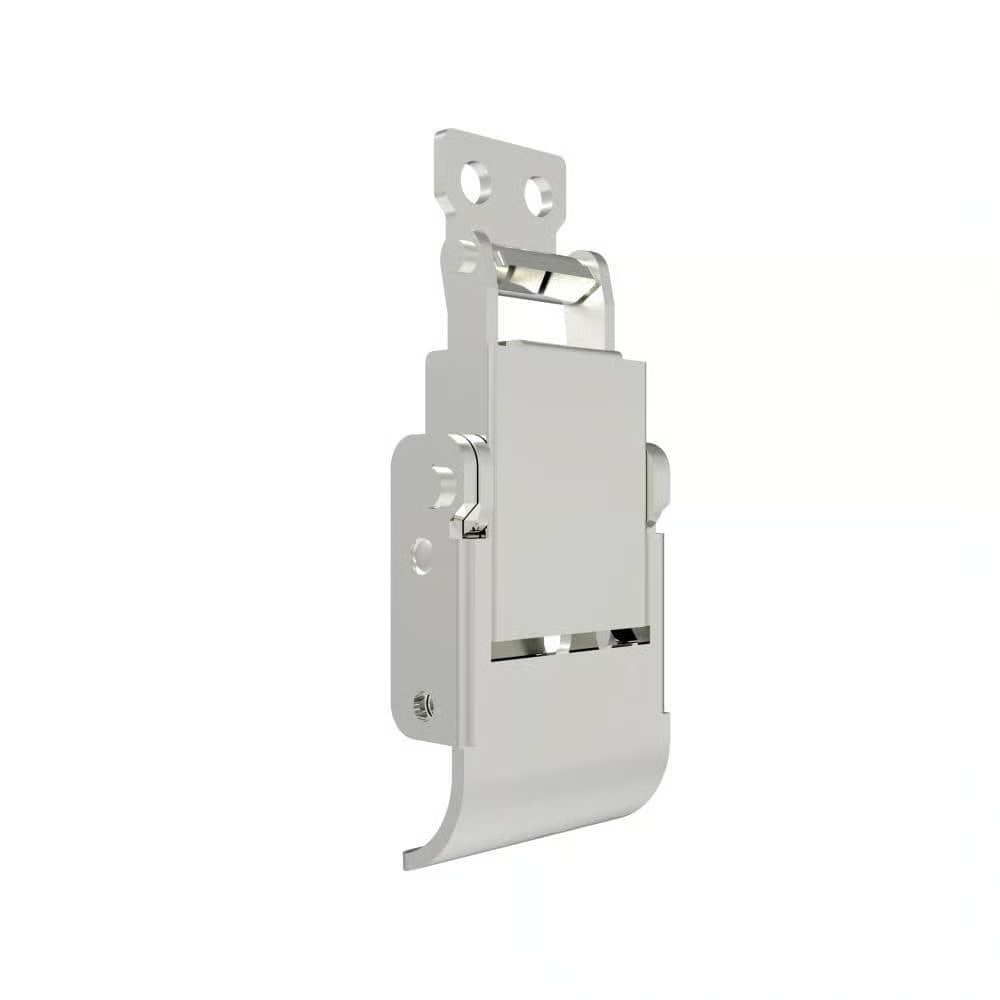
The handle provides the operator's input point. The pivot and linkage transfer that motion into the bail, hook or draw arm, which engages the keeper mounted on the opposite panel or frame. A mounting base secures the entire assembly to the structure, and many designs add an optional spring or safety catch to control handle position or resist accidental release.
The mechanism moves through three stages. In the open position, the hook is disengaged and the linkage is free. In the dead-center position, the pivot, linkage and load path align, representing the point of maximum operating effort. In the locked over-center position, the geometry has passed beyond dead-center so that separating force pushes the linkage further into its seated position rather than releasing it.
Handle movement creates mechanical advantage: a relatively small operator input force is converted into a larger clamping or preload force at the hook and keeper interface. This clamping force differs from holding capacity, which describes how much separating load the locked geometry can resist, and both differ from resistance to opening, which depends on handle accessibility, safety catches and friction rather than the over-center geometry alone.
For the mechanism to lock reliably, it must travel sufficiently beyond the center point, and the latch must be installed with the correct load direction relative to the keeper. Mounting geometry that is too shallow, too deep or misaligned can prevent stable over-center engagement even when the product is labeled as an over-center latch. A simple diagram showing the open, dead-center and locked positions is a useful reference when reviewing installation drawings with a supplier.
Which Types of Over-Center Draw Latches Are Available?
Over-center draw latches are commonly grouped by adjustment method, compliance and safety features, though many of these characteristics overlap within a single product rather than defining separate latch families.
Rather than treating every feature combination as its own category, it is more practical to think of adjustment method, flexibility and safety options as independent variables that can be combined according to the application. For readers who want a broader overview of draw latch types for heavy duty enclosures, background on hook, wire-bail and rotary variants can help frame where over-center designs fit within the wider draw latch family.
Latch Type | Adjustment Method | Compliance or Flexibility | Safety Option | Best-Fit Application | Main Limitation |
Fixed bail | None | Rigid | Optional catch | Stable panel geometry, high-volume assembly | No tolerance compensation |
Fixed hook | None | Rigid | Optional padlock hole | Consistent mounting distance | Sensitive to dimensional drift |
Threaded adjustable bail | Rotating shaft | Rigid | Optional catch | Variable gasket thickness or tolerance stack-up | Requires locking method, controlled setting |
Adjustable hook/keeper | Slotted or multi-position keeper | Rigid | Optional catch | Field-adjustable installations | Limited range, needs periodic check |
Spring-loaded | Fixed or adjustable | Semi-compliant | Often included | Minor movement, tolerance variation | Added component, potential fatigue point |
Flexible/elastomer bail | Fixed | Compliant | Rarely padlockable | Vibration or shock exposure | Chemical/UV sensitivity |
When Should You Choose a Fixed or Adjustable Draw Latch?
A fixed draw latch suits stable panel geometry and controlled production tolerances, while an adjustable design is justified only when tolerance, gasket thickness or compression variation genuinely requires field adjustment.
Fixed bail and fixed hook designs support consistent assembly outcomes when panel dimensions, gasket thickness and mounting-hole position are well controlled across production runs. They reduce the number of variables that installers or line operators can alter, which helps maintain repeatable clamping conditions.
Threaded adjustable bails and adjustable hooks or keepers earn their place when manufacturing tolerances, gasket thickness, panel spacing, assembly variation, or wear and compression changes over time would otherwise leave a fixed latch either too loose or overly tight. Adjustment lets an installer fine-tune the closed position without redesigning the mounting geometry.
Adjustability has real limits. It cannot correct a mounting base that was positioned incorrectly during panel fabrication. Excessive adjustment in one direction can sharply increase operating force, making the latch difficult to close by hand. Overtightening can deform brackets, panels or gaskets, and threaded components that are not secured with an appropriate locking method may drift under vibration. Because of this, assembly settings should be controlled and recorded during production rather than left to individual judgment. The core decision question is whether the application has a genuine source of dimensional variation—if not, a fixed design is usually the simpler and more consistent choice.
When Are Spring-Loaded, Flexible or Safety-Locking Designs Necessary?
Spring-loaded, flexible and safety-locking features become necessary when tolerance variation, vibration-induced rattle or accidental handle release present a real risk in the application, rather than as default upgrades.
Spring-loaded designs accommodate limited movement or tolerance variation by allowing the hook or bail to give slightly under load, reducing the risk of overstressing the mounting when dimensions shift within a small range. Flexible bail or elastomer designs absorb shock and reduce rattle in applications with continuous vibration, though their long-term suitability depends on the operating environment rather than the flexible element alone.
A secondary safety catch becomes relevant when accidental handle release is a genuine risk, such as in applications where the latch could be brushed or impacted during handling. A padlockable design supports access control by physically restricting who can operate the handle, but padlockability does not automatically increase mechanical load capacity; it addresses access, not strength. A larger or heavy-duty design may be appropriate when expected loads or panel size genuinely exceed the capacity of standard hardware, not simply because a bigger latch appears more robust. Spring loading, adjustability, safety catches and padlock holes are functional options that frequently coexist in one product rather than defining separate product categories, so specifying them should be based on the actual functional requirement, not a general size impression.
Which Materials and Finishes Suit Different Operating Environments?
Material and finish selection for an over-center draw latch must match the actual exposure conditions of the full assembly, not just the visible handle, because zinc-plated steel, 304 and 316 stainless steel and zinc alloy perform differently under corrosion and mechanical stress.

Zinc-plated carbon steel can be cost-effective for indoor or moderately exposed equipment, but if the plating is scratched, chipped or worn during installation or service, the underlying steel is exposed and corrosion can begin at that point. 304 stainless steel suits many humid and general outdoor environments, but it should not be treated as universally suitable wherever chloride exposure is present, since pitting can still occur under the right conditions. 316 stainless steel generally offers improved resistance in chloride-containing environments such as coastal or marine settings, but it is not corrosion-proof and can still be affected by sustained exposure, crevice conditions or inadequate cleaning. Zinc alloy components may suit specific cast parts and general industrial use, but the exact alloy composition and applied finish still determine real-world performance. Elastomer or rubber latch bodies provide compliance and vibration damping, but temperature range, UV exposure, oil contact and chemical compatibility need to be verified against the operating environment rather than assumed.
Finishes such as passivation, polishing, plating and coating can improve corrosion resistance or appearance, but they do not change the mechanical properties of the base material underneath. A latch with an attractive polished surface is not automatically stronger or more durable than one with a matte finish.
Environmental suitability should be judged across the complete assembly, including the handle, hook or bail, pivot pins, springs, rivets, mounting brackets and fasteners. A stainless steel handle paired with a plated steel pivot pin or a carbon steel bracket will not deliver uniform corrosion performance, so evaluating only the visible handle material can be misleading. A purchasing specification should identify the material grade, applied finish, critical component materials and expected exposure conditions; the phrase "stainless steel draw latch" by itself does not convey enough information for a reliable selection decision.
Where Are Over-Center Draw Latches Used in Industrial Equipment?
Over-center draw latches are selected differently across industrial applications because each closure faces a distinct combination of vibration, sealing, access frequency and accidental-opening risk that determines the required latch configuration.
Application | Main Operating Risk | Required Latch Characteristic | Typical Selection Concern |
Machinery guards and access panels | Vibration, frequent access | Stable over-center travel, cycle durability | Wrong draw distance causing binding |
Electrical/equipment enclosures | Sealing, dust/moisture ingress | Consistent gasket compression | Overcompression deforming gasket |
Transport and flight cases | Shock, repeated handling | Compliance, secure handle retention | Handle catching during transit |
Truck/trailer/mobile compartments | Vibration, road shock | Vibration-resistant hardware, corrosion resistance | Underestimating dynamic load |
Generator/HVAC access panels | Heat cycling, outdoor exposure | Corrosion-resistant material, sealing | Ignoring thermal expansion effects |
Agricultural/construction equipment | Dirt, impact, wide tolerances | Robust hook engagement, adjustment range | Insufficient adjustment for panel wear |
Outdoor/marine equipment | Chloride exposure, moisture | Appropriate stainless grade, drainage-aware mounting | Assuming stainless is fully corrosion-proof |
Industrial containers/removable covers | Frequent removal, stacking loads | Fixed geometry, defined load direction | Load direction not matching installation |
Machinery guards and access panels typically need the two components drawn together to maintain a stable barrier during operation, where frequent access and vibration make cycle durability and correct draw distance the main concerns; excessive or insufficient mounting distance can cause binding over repeated use. Electrical and equipment enclosures depend on consistent gasket compression for dust and moisture sealing, so the common error is overtightening the latch until the gasket takes a permanent set rather than sealing correctly.
Transport and flight cases face repeated handling and shock, so handle compliance and secure retention matter more than raw clamping force; a common failure mode is a handle that catches on surrounding structure during loading. Truck, trailer and mobile-equipment compartments experience continuous road vibration and shock, making vibration-resistant hardware and corrosion resistance important, with dynamic load frequently underestimated relative to static ratings. Generator and HVAC access panels undergo heat cycling and outdoor exposure, so thermal expansion affecting hook engagement is a frequent oversight.
Agricultural and construction equipment often has wider manufacturing tolerances and exposure to dirt and impact, so adjustment range and robust hook engagement are more relevant than fine finish quality; a common error is insufficient adjustment margin for panel wear over the equipment's service life. Outdoor and marine equipment introduces chloride exposure, where the selection concern is assuming any stainless steel grade is automatically sufficient rather than confirming grade and drainage-aware installation. Industrial containers and removable covers rely on fixed geometry and a clearly defined load direction, since inconsistent load direction between installation and actual use is a recurring selection mistake.
Which Engineering Criteria Determine the Correct Draw Latch?
The correct draw latch is determined by systematically evaluating load terminology, mounting geometry and the trade-offs among vibration resistance, sealing, safety and access—not by comparing a single catalog specification.

How Should Clamping Force and Load Ratings Be Evaluated?
Clamping force, working load, preload, proof load and ultimate load describe different measurement conditions and must never be treated as interchangeable when evaluating a load rating.
Operating force is the effort needed to move the handle; clamping force is the force applied at the hook-keeper interface; preload is the residual tension after closing; working load is the load the latch is expected to carry in normal service; holding capacity describes resistance to separation; proof load is a test load applied without permanent deformation; ultimate load is the maximum load before failure; and failure load is the point at which the latch no longer performs its function. These terms come from different test conditions and cannot be substituted for one another when comparing products.
Real application loads may include static separation force, gasket reaction force, vibration, shock, inertial load from moving equipment, panel movement, thermal expansion and misalignment between the latch and keeper. A catalog maximum load figure may represent a short-term test result rather than a load the latch can carry continuously. When multiple latches secure one panel, they may not share the load equally, and panel stiffness or mounting variation can concentrate load onto a single latch rather than distributing it evenly. Because application risk varies so widely, a universal safety factor should not be applied across every project; the allowable working condition needs to come from a combination of application risk assessment, manufacturer data and validation testing on the actual assembly.
Before accepting a load rating, buyers should ask: What type of load was measured? In which direction was it applied? What test fixture was used? Was the rating a working, proof or failure load? How many samples were tested? What defined failure? Was the keeper included in the test? Was the test static or dynamic? Is a recommended working limit available separate from the maximum figure? These questions replace reliance on a single unexplained number.
How Do Mounting Geometry and Adjustment Affect Latch Performance?
Mounting geometry and adjustment range directly control hook engagement and operating force, so an incorrect installation distance can prevent stable over-center locking even with a correctly rated latch.
Mounting-hole pattern, latch-to-keeper distance, hook engagement, draw distance, adjustment range, handle clearance, opening direction, panel offset, door and frame stiffness, fastener selection and mounting-area strength all interact to determine whether a latch performs as intended.
Too little mounting distance can create excessive operating force, making the latch difficult to close. Too much distance may prevent the mechanism from reaching a true over-center position, leaving the latch unlocked even when the handle appears closed. Poor alignment between the hook and keeper introduces side loading that accelerates wear or causes binding. Thin sheet metal can deform under clamping load if the mounting area lacks sufficient stiffness. An incorrectly adjusted latch may overload the gasket or the mounting bracket rather than distributing load as intended, and threaded adjustment that is not secured can shift position under vibration over time. Because these tolerances are specific to each product and installation, dimensions should always be confirmed against the exact product drawing rather than assumed from general references.
How Should Vibration, Sealing, Safety and Access Be Balanced?
Vibration resistance, sealing performance, safety catches and access frequency involve engineering trade-offs, so improving one characteristic often affects operating force or structural stress elsewhere.
Increasing preload can improve panel contact and sealing, but it also raises operating force and structural stress on the mounting and bracket. Elastic compliance from a flexible bail can reduce rattle, but it cannot correct mounting geometry that was set up incorrectly. Gaskets require an appropriate compression range; excessive compression accelerates compression set and can eventually reduce sealing performance rather than improve it. A safety catch reduces the risk of accidental release in applications exposed to shock or accidental contact, while a padlock hole restricts casual access but does not by itself demonstrate resistance to forced entry. Frequent-access applications call for attention to ergonomics, pinch points, handle edge design and expected cycle life, since these factors affect long-term usability more than static load capacity. Outdoor applications require both suitable materials and an installation approach that accounts for water drainage around the latch body.
A practical selection sequence follows from these trade-offs: define the closure function, identify static and dynamic loads, measure the installation geometry, determine whether adjustment or compliance is genuinely required, select material and finish based on real exposure, define safety and access features based on actual risk, and validate the sample on the actual assembly before committing to production.
How Should You Evaluate an Over-Center Draw Latch Manufacturer?
An over-center draw latch manufacturer should be evaluated on verifiable technical evidence—drawings, test definitions and process control—rather than general claims about quality or experience.
Can the Manufacturer Explain and Verify Its Product Ratings?
A technically capable manufacturer should be able to clarify the exact conditions behind every load rating, including test fixture, load direction and failure definition, rather than offering a single unexplained maximum-load figure.
Useful documentation includes complete dimensional drawings, material specifications, surface-treatment specifications, load-rating definitions, load direction, test-fixture configuration, cycle-test conditions, corrosion-test conditions, installation instructions, adjustment instructions and evidence of engineering change control. Buyers should be cautious about using a single unexplained maximum-load figure as the basis for design approval. Different manufacturers may use different test methods, and that variation is not inherently a problem—the important question is whether the method, sample size and result are clearly defined and relevant to how the latch will actually be loaded in service.
Can the Manufacturer Control Materials, Dimensions and Production Consistency?
Production consistency depends on documented control of critical dimensions, forming processes and material traceability, not on a general quality certificate alone.
Relevant evidence includes inspection records for critical dimensions, control over stamping, forming, casting, riveting or welding processes, consistency of pivot and rivet assembly, hook geometry accuracy, mounting-hole position, material traceability, plating or passivation process control, batch-to-batch consistency, a defined approach to nonconforming product, and engineering change management. A general quality certificate on its own does not substitute for product-specific process control and inspection evidence, and buyers should focus on the characteristics that directly affect fit, force, movement and durability rather than paperwork alone.
Can the Manufacturer Support Application Review and Custom Development?
Application and custom-development support should include drawing review, keeper positioning checks and a defined sample-approval process rather than open-ended customization promises.
A manufacturer capable of supporting real projects should be able to review assembly drawings, check latch and keeper positioning, provide 2D and 3D files, recommend fixed or adjustable configurations based on the application, review expected load direction, recommend materials and finishes, modify hooks, handles, mounting holes or safety features, produce samples, support installation evaluation, and define clear stages for custom tooling, sample approval and production release. For readers who want a structured way to compare suppliers against these points, detailed criteria for evaluating industrial latch manufacturers can help organize the review process into specific, checkable items rather than general impressions.
Evaluation Area | Evidence to Request | Warning Sign |
Load ratings | Test fixture, load direction, sample size, failure definition | Single unexplained maximum load |
Material specification | Grade, finish, critical component materials | Unspecified stainless steel grade |
Dimensional control | Drawings, inspection records, tolerance data | Missing drawings or dimensions |
Keeper compatibility | Keeper drawing, engagement data | No keeper data provided |
Sample process | Defined approval steps, revision history | No sample verification offered |
Production consistency | Process control documentation, traceability | Uncontrolled product substitutions |
Custom development | Defined tooling and approval stages | Customization promises without an approval process |
How Should Draw Latch Samples Be Validated Before Production?
Draw latch samples should be validated on the actual or representative panel assembly through a defined sequence of checks, because desktop hand-operation alone cannot confirm installed performance.
A practical validation sequence includes: comparing the sample against the approved drawing; installing it on the real or representative panel assembly; confirming hook engagement and over-center travel; measuring or evaluating opening and closing effort; inspecting the latch, keeper, panel and brackets for deformation; checking gasket or flexible-element compression; conducting relevant cycle, vibration, shock or corrosion testing; rechecking wear, looseness, alignment and function after testing; recording the final adjustment and installation method; and retaining the approved sample and drawing as a reference for production inspection.
Hand-operating a latch on a desk does not validate how it will perform once installed under real mounting geometry and load conditions. A single tensile failure test does not establish cycle life, since repeated operation introduces wear mechanisms that a one-time pull test cannot reveal. Salt-spray test hours cannot be directly converted into an expected field service life, because actual environmental exposure differs from accelerated laboratory conditions.
Neutral Salt Spray Test for ForndLock Lock
A manufacturer's component-level test also does not validate the customer's complete assembly, since panel stiffness, bracket design and installation quality all affect real-world performance. Test conditions should be chosen to reflect the actual risks of the project and any applicable specifications relevant to that application, rather than relying on generic test parameters.
How Can ForndLock Support Your Draw Latch Project?
At ForndLock, our engineering team supports draw latch projects by reviewing application drawings, panel and keeper geometry, and expected load direction before recommending a product direction. We also review vibration and shock conditions, gasket requirements, material and finish requirements, safety and access requirements, installation constraints and adjustment needs. Where a project requires a modified hook, handle or mounting configuration, we work through customization requirements and sample-testing plans alongside the customer's own engineering team, so that decisions are based on the specific assembly rather than general assumptions. This review process is intended to clarify installation geometry and functional requirements early, before tooling or production commitments are made, reducing the risk of mismatched mounting distance, incorrect load direction or unsuitable material selection later in the project.
ForndLock Industrial Lock Series
Conclusion
Selecting an over-center draw latch starts with confirming that over-center draw action genuinely fits the closure function. From there, choose fixed, adjustable or flexible construction based on real tolerance and movement needs, and match materials and finishes to the actual operating environment rather than a general description. Keep clamping force, working load and ultimate load clearly distinct when reviewing any rating. Evaluate manufacturers using drawings, clearly defined test conditions and documented process control rather than general claims. Finally, validate the finalized latch on the actual assembly before committing to production, since installed performance depends on geometry and conditions that a desktop check cannot reveal.
Need an Over-Center Draw Latch Manufacturer for Your Application?
If you are selecting or customizing over-center draw latches for a new design or an existing closure problem, ForndLock can support product selection, drawing and installation review, material and finish recommendations, custom latch development, sample evaluation, project quotations and production support. To begin a review, please share your drawings, installation dimensions, expected load direction, operating environment and functional requirements.
Email: [email protected]